
Voltage Tracker for Oscilloscope
My Digital Oscilloscope has a timebase of maximum 50 seconds per DIV and a 12 DIV screen, which gives a mere 10 minutes for following a voltage. Much too fast to track charging or discharging batteries or other slow changing events. An Arduino Mega 2560 with the here introduced shield expands the oscilloscopes tracking time up to 12 hours, or more.
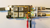
The Shield consists of four push buttons, a digital to analog converter, a negative supply, a rail to rail operational amplifier, two input and output jacks, a control LED and some connectors, resistors and capacitors.
The Arduino Mega plus shield can be powered by USB or a 7.5 to 12 V mains adapter.
K3 is the input for the voltage to be traced. Two BNC plugs are connected to the oscilloscope, one for the signal and one serves as trigger source. The - and + buttons (S1 and S2) decrement and increment settings. Set button S3 starts settings and cycles through them. A short press on S4 starts or stops tracking, a long press deletes the current tracking curve.
LED1 stays dark in setting mode, blinks while tracking and will light constant when tracking is stopped.
The oscilloscope does not have to run during tracking and can be switched on and off at any time, without loss of results.
For normal operation the oscilloscope’s time base should be set to10 ms/DIV and vertical 2 V/DIV.
All settings are stored in the Arduino’s EEPROM.
Here in the Elektor Lab we first considered to replace the –with all due respect- old DAC0808 with a more recent digital-to-analog converter. However, the author convinced us that this part is cheap and available in many (online) electronics shops. Moreover, many of our readers will still have this part in their (junkbox) parts stock, so why switch to a more expensive newer component which will probably only be available as an SMD part? We had to agree, we just made some smaller changes to the original design.
First of all we noticed that there was no protection on the analog input of the circuit. We added a series resistor plus two clamping diodes to the input, that was directly coupled to an analog pin of the Arduino Mega board. Wrong polarity or input voltages exceeding the circuit’s 5V power supply could have easily damaged the Arduino. It’s still no full proof protection, but it will do its job for most (short term) connection errors.
Now we’ve mentioned it: note that the input voltage on K3 should not exceed 5V! Use a voltage dividing network if you want to measure higher voltages (like the (dis-)charge curve of a 12V car battery).
The author used an OPA347 operational amplifier in his design. Although this IC is still being produced in SMD, the version in DIP8 case is out of production and very hard to find. Fortunately in this design almost any other rail-to-rail OPAMP will do, we decided to use Microchip’s MCP601 instead.
Assembling and soldering the circuit will not be too difficult, all parts are through-hole mounted and there is enough space on the PCB we designed. Put the shield on your Arduino Mega, connect it to your PC using the USB cable. Download the voltage tracker’s sketch and perform the standard compiling/programming cycle in the Arduino IDE and your tracker is ready to be used.
The voltage tracker can be configured by pressing Set (S3). There are five parameters that can be adjusted: time, level (offset), roll mode, Y-scaling and the number of time divisions on the oscilloscope’s screen. Repeated pressing of S3 cycles through these five parameters, - and + (S1 and S2) will change the current setting. On the scope’s display you’ll see one character indicating the parameter (t, l, r, y and n respectively), followed by a ‘staircase pattern’ indicating the current setting of this parameter.
Pressing S4 (Start) exits the settings mode and starts the measurement.
Time
There are seven settings possible for this parameter, which determines the maximum time interval that will be displayed on the oscilloscope. Note that the values in the table below are only correct for an oscilloscope with 12 time base divisions, don’t forget to set the fifth parameter ‘n’ to match the number of divisions of your oscilloscope!
Steps Time/DIV Duration (@ 12 DIV Screen)
1 1 min 12 min
2 2 min 24 min
3 5 min 1 h
4 10 min 2 h
5 20 min 4 h
6 30 min 6 h
7 1 h 12 h
Level Setting
Steps Offset (@ Vcc 5 V)
0 0.0 V
1 1.0 V
2 2.0 V
3 3.0 V
4 4.0 V
For example the zero level on your scope will be set to 3.0 V when steps is set to 3.
In cooperation with y-scale setting, be sure to make meaningful adjustments.
Roll Setting
Steps Screen Roll
0 OFF
1 ON
With roll OFF tracking stops after a full screen.
Roll ON will scroll the screen after it is full. Values on the left are deleted one by one, while
current measurements appear on the right.
Y-Scale Setting
Steps Osci Y Range Level Max
0 1/4 1.25 V 4.0 V
1 1/2 2.5 V 3.0 V
2 3/4 3.75 V 2.0 V
3 1/1 5.0 V 0.0 V
Example
Oscilloscope y (vertical voltage) at 2V/DIV
shield y-scale at 0 = 1/4
-> 0.5V/DIV on oscilloscope (2V * 1/4)
A level setting of 3.0 V with y-scale 0 (range 1.25 V), means the voltage will be tracked between 3.0 V and 4.25 V, best suited for tracking LithIo (dis)charging.
In cooperation with level setting, be sure to make meaningful adjustments.
Number of DIVs Setting
Steps Divs
0 10
1 11
2 12
3 13
4 14
5 15
6 16
Sets the number of horizontal DIVs of the oscilloscope.
Example
Discharge of a LithIo Battery, stopping the discharge at about 3.3 V. After that the recovery of the cell to a level lightly lower than before discharge.
Shield time setting 1 min / DIV -> total screen 12 min.
Shield zero level 3.0 V and y-scale 0 (1/4), oscilloscope y at 1V/DIV makes 0.25V/DIV
Want to build a project?
Bring your design to life with the Elektor PCB Service, powered by Eurocircuits. Upload the project files and order professionally manufactured PCBs or assembled boards through a proven European production platform.
Supporting KiCad, Eagle, Gerber, and ODB++ formats, the service is suitable for everything from prototypes and validation builds to series production and volume manufacturing.
Made in Europe. Fast. Reliable. Professional.
Discussie (1 opmerking(en))