HV Power supply with tube and semiconductor curve tracer

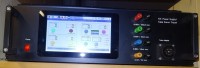
HV power supply with tube and semiconductor curve tracer controlled by a Raspberry Pi with touch display.
This versatile equipment can either be used as a power supply for tube experiments, or as a curve tracer. Originally, it was planned as a tube curve tracer, but during development, the idea came up to extend the functionality to a semiconductor curve tracer – especially for high voltage transistors/ Mosfets and Zenerdiodes. It is controlled by a Raspberry Pi (model 2 or 3) together with a 7” touch screen. Voltage and current can be controlled via virtual potentiometers on the touch screen. Actual voltages and currents are displayed via “7 segment displays” also located on the touch screen.
Discussie (16 opmerking(en))
R. Hesemann 2 jaar geleden
das Layout enthält weitere Fehler !!!
Thomas Bunge 4 jaar geleden
Limitations:
- one remote supply board only supported at the moment
- reaction timing a bit sloppy due to limited hardware power (I use a Raspi 4b, 8G RAM)
- bit-banging on SPI only (I stole Rainer‘s code, I added credits) I pulled my hair but couldn’t get Spidev running, simply no response from the devices, I guess some kind of timing issue
- probably some kind of spaghetti code in the eyes of a pro Python programmer (feel free to improve :)
Todo:
- add some +/- button above and beneath the sliders, although you can click inside the slider to change values at small increments, once the slider is close to upper / lower limit you can’t click inside :(
- add presets
Notes:
Look through the comments here to find my LTSpice simulation of the analog part of the remote supply board. This will become handy to change components to support different output parameters.
Do not forget to add the short circuit improvement shared by Rainer here in the comments as well.
And last but not least, see my comments about C compiling on the Raspi itself. With the release of Raspi 4b the whole development can be done directly on the Raspi. No more jumping through hoops on a remote PC to compile for the Raspi platform. Install qt-default and QtCreator on Raspian and you’re ready to go. Just import Rainer‘s project and add the wiringPi library as external system library (w/o importing any paths!). You do this through a right-click on the project in project main view (took me a while to figure this out). Through VNC or connecting a big screen you can actually do the form editing directly on the Raspi as well (QtDesigner is installed now by default). Leave a reply if you need help...
Thomas Bunge 4 jaar geleden
Jiri Cerny 4 jaar geleden
About a year ago, I finished working on the hardware of this excellent device and I would like to share a few insights from its use and further development.
During the construction, I used all the experience and improvements that my colleague Ivo Procházka consulted with you (see the contributions in this discussion). Adding protection transistors to the outputs proved to be very useful.
Colleagues working on the restoration of historical radio technology, or the construction of replicas, expressed the wish that it would not be possible to add the possibility of measuring pentodes in the "pentode mode" (with a constant Ug2).
To do this, it was necessary to make a few minor changes to the software:
1) Add the option to enter the required Ug2 (the originally unused field "Delta Ug2" of the form "CubeTraceWindow" was used for this).
2) In the "pentode measurement" mode, block the measurement stop when Ig2max is exceeded. (Instead of stopping the measurement, the maximum current through the grid is hw limited to the Ig2max value, but the measurement continues. It is necessary to correctly interpret the measured values or adjust the input values and repeat the measurement. If the "Stop at Ig2max" function remained on, the measurement in the "pentode" mode would be very inconvenient, as the maximum Ig2 current flows at the beginning of the measurement until Ua << Ug2 and it would be necessary to enter the input parameters experimentally to start the measurement at all and did not end with an error message. The current through the grid is sufficiently limited by the controller hardware and the moment of transition to the constant voltage mode is clearly legible in the graph.)
3) Move the legend in the "pentode mode" to the right part of the graph, because the "more interesting" part of the graph is (unlike the "triode mode") on the left and is therefore not covered by the legend. The x-axis label is modified in the same spirit.
4) Add a button to select whether to measure in "triode" or "pentode" mode and modify subsequent procedures.
When modifying the software, I used the version provided by Ivo Procházka (modified "MainWindow"), because this control is more convenient than the original (albeit elegant, but uncomfortable) virtual potentiometers. The executable file for Raspi and modified source codes are available in the attachment.
I welcome comments on this edit.
Regards
Jirka
20210105-132819.jpg (833kb)
v_3_0_1.zip (3324kb)
pl-84-t.png (64kb)
pl-84-p.png (78kb)
Rainer Schuster 4 jaar geleden
Great work!
I always shifted working on this feature because I knew that it was a lot of work.
So I am very happy that you did it and it works also fine on my device.
I'm also very sure that other Elektor Readers who have built this device are also very happy of this feature.
Best Regards,
Rainer
ivo prochazka 5 jaar geleden
Few days ago, I finished the hardware work on thiis beautifulll project and now I would like to share with you and other users of CubeCurveTracer some experiences and plans. I have some questions too.
1. I have made some improvements In MainWindow_new. There is only some design change which more corresponds to my thick fingers and maybe this design is safer from quick finding pushbuttons point of view. In addition I changed the preset 12V in heating power supply to 12.6V which is more in line with the reality of tubes heating. You can find this changed project in attachment. This includes executable file and MainWindow QT file.
2. I have just started my next work on the project which will be the implementation a rotary encoder to change the way how to change input values to eliminate need of the keyboard. What do you think about this idea?
3. During the tests I found some inconsistency in the behaviour of the power supply. For example (using new GUI) until I set the current limit of Anode power supply to at least 4 mA I cannot reach the maximum output voltage of 400V. Of course - these values correspond to the quiescent current through the resistor R15. Maybe it would be a good idea to plug upper outlet of this resistor R15 from GND to the left side of R7 (connected to the FET as well). This will hopefully eliminate measurement of this quiescent current but I don’t know if it will affect the internal calculations for the Curve Tracer mode.
4. I would like to discuss with you one unfortunate thing that has happened to me.
During the anode supply tests, (which worked well including current limitation), I made accidently short circuit to the output terminals (at the seting of maximum voltage and current). The result: burnt Q6, R14 (!!!), R11, LT1079, LT 1078 and fuse – most expensive parts of the board. I don’t know why current limitation did not work in time, short circuit is after all normal if we use laboratory power supply, BUT: The destruction of Q6 (short circuit between of all electrodes, because of not working current protection) and subsequent interruption of R14 (1 Ohm/2W!!!) caused full voltage 400V to be sent to LT1079 and LT1078 and they were destroyed as well.
My suggestion is to significantly increase the power of R14, which must never be destroyed to open circuit. This will at least protect the expensive IC’s. In fact, the fuse must be blown earlier then the R14. However, this still does not solve why current protection by short circuit did not work. After replacing of all burnt parts the board works again well. I'm now a little bit afraid of trying another short circuit :-)
Thank you for any comment(s)
ivo prochazka 5 jaar geleden
Rainer Schuster 5 jaar geleden
You're right - the "I - behaviour" of the current limit circuitry causes a delay of 2.5ms!
During this time, the power dissipation of Q6 exceeds the safe operating area of the transistor on a "hard" short circuit. This damages Q6 with all the faults you described.
But you cannot simply reduce this delay - lower values of R24 and/or C8 will result in an oscillating current limiting. But I found a simple way to limit the current to 0.7A without any delay by adding a transistor like shown in the attachment. After the delay time , the current will then return to the adjusted value.
ivo prochazka 5 jaar geleden
Thomas Bunge 5 jaar geleden
ivo prochazka 5 jaar geleden
Rainer Schuster 5 jaar geleden
to be honest, I never tried such a "hard" short circuit. Therefore I first have to investigate this problem before I can offer you a solution.
ivo prochazka 5 jaar geleden
please, can you tell me the missing values of the resistors on distribution board?
Many thanks,
Ivo.
Thomas Bunge 5 jaar geleden
Rainer Schuster 5 jaar geleden
R1 and R2 are 100 Ohms each.
Thomas Bunge 5 jaar geleden
The following changes are required.
On the respective remote supply board input needs to be at least 150V and change R17 to 390k and on the hardware.h header file change the following declarations:
#define GRID1_VOLTS_MAX_BITS 870
#define GRID1_MAX_VOLTS 140.0f
#define GRID1_VOLTS_CORR_FACTOR 0.04865f
They to be found in three different sections of this header file. This btw. Is the recipe to change voltages and currents supplied by the boards. It requires to rebuild the app. If you install the standard Qt backend through
sudo apt-get install qt5-default
sudo apt-get install qtcreator
you can install Qt 5.7.1 and Qt Creator 4.2 on the Raspi. This will allow building directly on the Raspi. A 3B is highly recommended. Rainer’s VIsual GDB Project can be directly imported. Set the right arm (found in /usr/local/lib/bin/arm...) g++ compiler and don’t forget to include the wiringPI lib. Do not include the paths (only this one lib!) or the compile will fail since qmake won’t find its libs any longer. Use a QtDesigner on a host PC and copy files over. Editing the GUI on the Raspi is a pain.
steven Desse 5 jaar geleden
Thomas Bunge 5 jaar geleden
When I connect more then one Remote Power Supply Boards to the Distribution Board the Raspi won’t boot. The only solution I’ve found is to separate the 5V power supply from the Raspi and the supply of the 5V to the Remote Boards (I split the flat cable and applied a switch). I believe it’s some kind of Latch Up preventing the Raspi to boot. Here’s the sequence I found out works:
Power up everything (all 13 leds light up, Distribution Board Power (4), Raspi Power (1), Remote Supply 12V power rails (4x2). Consequence, Raspi won’t boot. The moment I disconnect the 5V power to the Remote Boards Raspi starts booting. A split second switch is sufficient, Off/On. From there on everything works like a charm.
I am afraid to proceed with that procedure with the Remote Boards fully powered up because I am concernd about Latch up of the OP amps seeing input voltage without power supply. On the other hand this scenario is present every time you power down the unit due to the remaining charge in the power condensators (on the Anode supply for a few seconds even).
I guess R17 will constrain the input current to a maximum of about 0.5mA. In that case my procedure should be ok.
What do you think???
Equipment used:
Original board design with Micro connectors and external separate 5V switching power supply. Raspi 3B+ with 1024x600 HDMI touch display. Original software with uptodate Raspian.
Thomas Bunge 5 jaar geleden
Add:
i couldn’t sleep and fixed the DAC as well. I get 400V now. ADC, DAC and voltage output at the terminals all now within +-0.3% (1V) accuracy. Good enough...
I carefully selected components, especially Oamps resistors and did the fine tuning via software modification, mainly applying linear regression curves of the form y=a*x + b to calibrate output of the read_ADC, check_Anode_supply and check_Grid2_supply functions. Grid1 and heater are ok.
That’s it for me. I Will probably use and apply this concept for other voltages and currents for general purpose programmable power supply’s...
Thomas Bunge 5 jaar geleden
Rainer Schuster 5 jaar geleden
yes - you can adjust the voltage with R17 (R5 for current calibration).
And yes: It would be nice if you could send me your forms for the higher resolution display.
Thanks in advance
Thomas Bunge 5 jaar geleden
when it comes to precision, especially on the voltage, which resistor(s) on the remote supply board would need to become adjustable resistors for calibration purpose, R17?
Let me know if you’re interested in my forms for 1024x600 resolution. They look good and the bigger buttons are better to hit on the touch display:)
My picture reveals a ~1% inaccurate voltage tracking on the anode supply. Not dramatic, but with the digital display it’s intimidating for a German engineer :)
greetings from Canada
Thomas Bunge 5 jaar geleden
Greetings from Canada
Rainer Schuster 5 jaar geleden
sorry again - here the zip file with the Mainwindow header file added.
Thanks for the nice pictures - very well done!
Greetings from South Germany
Thomas Bunge 5 jaar geleden
I guess Mainwindow header file is missing in your attachment. Some declarations missing resulting in compile error...
I was planning to change the GUI as well in that perspective. You saved me a lot of work. :)
The QT setup on the Raspi is not difficult. But configuring a project is, since the Arm version is buggy as hell. I have to reset the project every time I do a new compile, but it works. As a proof see the increased version number.
I’d really like to use your new mainwindow, so if you could send me the Mainwindow.h file as well...
Greetings from Canada
Assembled (1910kb)
Rollerfischer Trafo (1941kb)
Running (old) software compiled (1306kb)
Rainer Schuster 5 jaar geleden
Congratulation! - You made it work without VisualGDB - I'm impressed!
And yes of course I'm very interested in pictures of your build.
BTW:
After one year experience with this equipment it turned out that the virtual potentiometers are in fact funny, but not very useful - especially when you want to setup accurate voltage/current values. So I replaced these potentiometers by up/down buttons and added individual On/Off buttons for each supply. Now you can preset the desired values and then you can switch on and off each supply.
I uploaded the altered sourcefiles in the attachment.
Thomas Bunge 5 jaar geleden
Great project! Let me know if you are interested in some pictures about my build.
Greetings from Canada!
Thomas Bunge 5 jaar geleden
objectName No_of_curces needs to be No_of_curves or you’ll get a compile error for a missing reference in TransistorCurveTracerWindow.cpp.
Typo. The headerfile included in the sourcefile zip has the correct objectName. So this issue will not strike until you change something in the form and create a new header file. You should not change the headerfile directly since every change of the form in QtDesigner will overwrite your changes.
Btw. I was unable to get crosscompiling going so I did install Qt on the Raspi and compiled directly on the Raspi while doing the form change on my desktop and just export the headerfile.
I still have difficulties with the project configuration since the project file generated by VisualGDB is incompatible with the QtCreator config file. I am not an expert and would need help setting this up. I want to avoid the need of buying VisualGDB since QtCreator is for free!
Thomas Bunge 5 jaar geleden
Good thing, I didn‘t fry the Raspi or any OP amps and most important, I found the issue myself while learning a lot.
That proves that even at an age of 60 one can learn stuff :).
Next thing, I will try to modify the source to adapt the GUI to LCD resolution 1024x600 and use the whole screen.
I really like the concept a lot since it’ll allow different power configurations as well.
Rainer Schuster 5 jaar geleden
sorry - this is a mistake in the Eagle files which I uploaded later (wrong version)!
I also encountered this problem and removed R20 from the remote supply board.
Thomas Bunge 5 jaar geleden
Add: I have disconnected R20 on all Remote Power Supply Boards and the boot problem is gone.
Please comment...
Electron35 6 jaar geleden
Je vais en suivre l'avancé.
Christian
Thomas Bunge 6 jaar geleden
Can you share the Eagle or Gerber files?
This is the tool I always wanted. Where can I order the PCBs? Please also share a component list. I assume Audioelektronik would be able to wind the Transformator for 110V input (I am from Canada).
Vielen Dank für das tolle Projekt! Many thanks for the wonderful project!
PM: thomas@laserhunt.ca
Thomas Bunge 6 jaar geleden
the $200 were for 5 boards only :(
R. Hesemann 6 jaar geleden
(5 are the minimum order quantity)
I have often there ordered , high quality pcb's and fast production / shipping!
phase2682 6 jaar geleden
Thomas Bunge 6 jaar geleden
I would be able to have the PCBs produced, preferably as a batch order. Still not cheap, ~$200US for the 5 boards (4x Remote-supply, 1x Distribution board). The two companies I was looking at: one in China (https://www.pcbcart.com) and one in the US (https://oshpark.com/). The US is my preference, since they offer free shipping and also accepted all Gerber files from scratch and it looked great! But they do not accept minimum orders, need a set of three. The China company accepts one-of.
Btw. did one of you guys made a layout for the semiconductor adapter board. It has been a while since I last worked in Eagle :). Please share at least the .brd file.
I see this project as an opportunity for a universal power supply unit with unbeatable tracking features...
Many thanks again to Rainer for his idea and work!
Yuri Vorobets 6 jaar geleden
R. Hesemann 6 jaar geleden
Yuri Vorobets 6 jaar geleden
GEORGE LYDECKER 7 jaar geleden
Thomas Bunge 5 jaar geleden
Could it be, that you have a mistake? The step down converter (out+) is connected to pin 1 of the thyristor cathode and the (out-) to pin 2 anode? Reference: your new pcb you shared...
From my point of view that wouldn't present a harm to the circuit but no function either. Please clarify...
Thomas Bunge 6 jaar geleden
R. Hesemann 6 jaar geleden
wird als 110V Ausführung wahrscheinlich günstiger !
Thomas Bunge 6 jaar geleden
I have found a better option https://tube-audiodesign.hpage.com/netztrafos-ac-transformers/hochvolt-transformatoren.html#top
waiting for an official offer, but will be in a range of 80EUR for a 220VA RK Trafo! Will come with 115/230V primär and has ~10days delivery.
Thomas Bunge 6 jaar geleden
R. Hesemann 6 jaar geleden
Thomas Bunge 6 jaar geleden
R. Hesemann 6 jaar geleden
https://www.aliexpress.com/item/500W-toroidal-transformer-small-power-supply-transformer-220V-to-24V/32988120424.html
Thomas Bunge 6 jaar geleden
where did you order the Trafo in China?
happy Easter!
R. Hesemann 6 jaar geleden
which resolution does the software/display need, 800 * 480?
happy easter
R. Hesemann 6 jaar geleden
try to stop, i think the company does not produce on the weekend!
the *.bmp is for "diy self-etcher", there is no stop mask, in the double-sided is all right with me!?
Yuri Vorobets has changed his sprint layouts to normal 2.54mm pins!
I did that also with my eagle boards and changed a lot of others.
I have additionally a 5V 3.5A supply for the raspberry and the display
(step down converter and crowbar), everything pushed together and some components changed e.g. bridge rectifiers instead of single diodes.
what i have not in stock at components i order for example at aliexpress.
The transformer with an additional 8V winding I have just ordered too in China as toroidal transformer, 60USD including DHL shipping, let's see if that works!?
happy easter
Thomas Bunge 6 jaar geleden
p.s. What type of 10x2 pcb connectors is Rainer using to connect the distribution board with the power supply boards?
R. Hesemann 6 jaar geleden
Thomas Bunge 6 jaar geleden
R. Hesemann 6 jaar geleden
aber bitte nochmal kontrollieren ! Größe wie das org. 54x92mm
Gruß und frohe Feiertage
Thomas Bunge 6 jaar geleden
Everything worked out ok. Any chance you can share the Semiconductor Adapter .sch and .brd too? Just saw this board is double sided too...
Kind Regards,
Thomas
Rainer Schuster 6 jaar geleden
I uploaded the Eagle-files as you requested. You can export the partlist directly from eagle with File->Export->BOM (or Partlist)
Christian Herr 6 jaar geleden
Rainer Schuster 6 jaar geleden
Rainer Schuster 7 jaar geleden
Now I was able to upload the software (after removing some garbage produced by Visual Studio).
Concerning the transformer question from Christan Herr: It can be ordered on "http://www.audioelektronik-shop.de/", order BV019/4666 as also mentioned in the General schematics.
Christian Herr 7 jaar geleden
Moises Escobedo 7 jaar geleden
Thanks for sharing it.
Let us know were we can get the project files...
Thanks.
Ioannis D. Kyriakidis 6 jaar geleden
I am in such Power Supplies with outputs up to 500V and 500mA and am concerning about the losses. Much preffered the SMPS but having it in the range 30-500 is too difficult.
I ended up with SCR's in the rectifying circuit and the SCR's controlled by the difference in the smoothing cap and output through a zener. That way the dropout is kept around 10 volts because the SCR's are switching on/off and they keep lower input voltage to the FET regulator.
The down side is the clicking noise that is heard from the transformer. I am using a torroid that usually has no laquer on the windings.
Rainer Schuster 6 jaar geleden
as also mentioned in the description, the SK129 heatsink is only suitable for the control grid regulator. The maximum power dissipation there is 140V * 30mA = 4,2W which can be easily handled by this heatsink. All otherpass transistors must be mounted on an external heatsink.
Ioannis D. Kyriakidis 6 jaar geleden
Ioannis
Johan Marselje 7 jaar geleden
Christian Herr 7 jaar geleden
this is a great project. Maybe you could place the project files on github. It should be possible to place larger files there. I would like to build this project, since I regularely have to check my tubes and have another dead transistor amp that is worth repairing. At the moment I just can check my power tubes by adjusting the bias and carefully listen to them while playing. Would be nice to "see" them working...
Could you please provide some data about the transformer and where I could get the software part (TubeCurveTracer Apllication)?
Thank you.
ClemensValens 7 jaar geleden
Rainer Schuster 7 jaar geleden
sorry, but the (zipped) size of the whole project (incl all source code) is abut 129MB!
We have to select another path for uploading the software.