
Mains Power Driver by MCU DC or PWM
There are not so many projects on the web where you can drive a mains power using a TRIAC. This project can drive 2000 watt by a DC or PWM control.
There are not so many projects on the web where you can drive a mains power using a TRIAC. This project can drive 2000 watt by a DC or PWM control.
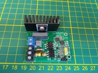
I did not want to use the MCU timers to control the 50Hz phase control. The setup also need to be able to drive inductive loads. So I defined a pulse driven solution controlled by a DC output or an PWM output of an MCU. The unit is perfectly running using a simple Arduino. Schematics, PCB and Arduino code is available. The picture is from a simple unit where an Arduino and all mains stuff is build in one box.
I am not sure whether mains connected projects are allowed here, so once I see people are interested I will publish more details.
Updates van de auteur