

CO2 Guard [210043]
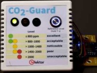
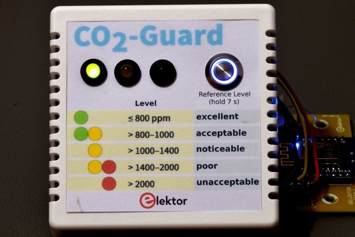
CO2 400-2000 ppm, 3 LED's , level/temp sensor logged to ThingSpeak, buzzer, ESP8266
Designed by Florian Schäffer
This CO2 Guard is used for indoor air monitoring and assessment of the air quality (IAQ: Indoor Air Quality) based on the carbon dioxide concentration. A CO2 concentration in the interior of less than 1000 ppm (0.1 vol%) indicates a hygienically adequate air exchange under normal conditions and can help to minimize the risk of infection with COVID-19.
About the circuit
Heart of the circuit is a Wemos D1 mini, a small Wi-Fi board with 4MB flash based on ESP-8266EX. It’s used to get data from the sensor MH-Z19C by I2C, drive three LED's for indication of the CO2 levels, drive a buzzer to serve as an acoustic alarm when levels are unacceptable, supply 3.3 V for a miniature fan, supply 5 V for the sensor and an extra led inside a switch to indicate a W-Fi connection is active. The micro-USB connector serves as power supply. A 5VDC AC adapter with micro-USB connector is needed as a power supply for the CO2-Guard. The switch is connected to the sensor to perform a calibration. According to the datasheet the sensor must be active in an environment with 400 ppm CO2 level for more than 20 minutes before the HD input is pulled low for over seven seconds by S1. The manufacturer calls it zero point calibration, but we prefer the term reference level since calibration is done at 400 ppm. If not performed by hand calibration is done automatically every 24 hours if continuously powered by taking the lowest level measured as reference level. Outside the air is about 400 ppm and this CO2-Guard is meant for rooms that aren’t used by people full time, let’s say only during normal working hours.
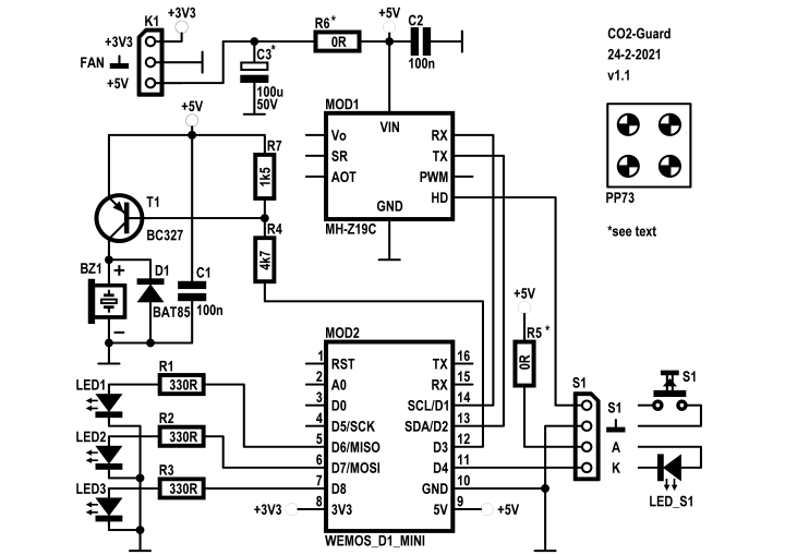
The 5 V fan is connected to the 3.3 V output of the D1 mini via connector K1, to make it run more silent and cause less airflow. Feel free to solder the wires directly into the PCB if so desired. Dust build-up will be less with less airflow. The 3.3 V on the module is created by a ME6211 regulator in a SOT23-5 package. Maximum dissipation of the regulator is 250 mW and this will limit the maximum current of the 3.3 V output of the D1 mini to less than 150 mA. It's. not advisable to use this (theoretical) maximum output current. It’s not specified by the manufacturer of the board(?). To avoid this “heavy” load on the 3.3 V regulator there’s an option on the PCB of the CO2-Guard to connect the fan through a resistor (R6, footprint for 1 W type) directly to the 5 V. This makes it possible to reduce the airflow even further. But, a too high resistor value and the fan won’t start at power-up. A capacitor (C3, 100µF) across the fan can lower this voltage level but should be tested before mounting the final R6 and C3. It depends on the fan used, even a fan from the same series can give a different maximum value for R6. It also depends on temperature rise of the fan! If the fan is to be connected to the 5 V directly a wire jumper wire can be used for R6 instead.
The buzzer also uses the 5 V supply. The output level of the I/O’s of the D1 mini when high is 3.3 V. To turn the buzzer off voltage divider R4/R7 is connected to the base of PNP transistor T1. Some buzzers are inductive and likely to produce spikes, especially when turned off. Diode D1 prevent these spikes from harming the transistor. De buzzer has a footprint with a pitch of 5 and 7.62 mm, so there’s also a pitch of 6.31 mm where a buzzer with 6.5 lead spacing should fit.
The switch (momentary on) we used is one with an optical indicator in the form of a blue ring. No resistor is needed for the led in the switch. + and – next to two pins of the switch indicate the two connections of the LED. The other two pins are connected to the switch. Four wires (three with common ground for led and switch) are connected to a 4-way pin header (or solder the wires directly to the PCB). If the circuit is used in a different setting a separate switch and LED can also be used. R5 sets the current for the separate LED. Here R5 is not needed and a jumper wire should be used in it’s place on the PCB (next to D1).
Make sure no wires lie on the antenna when the top is finally placed on the bottom part of the enclosure. Keep them as far away as possible but don’t make them longer than absolutely necessary. Wires to the switch can be as short as 8,5 cm and the wires to the LED's about 12 cm. With this length of the wires you can remove the top of the enclosure and place it on its side next to the bottom with all wires still attached. No screws are used to attached the two parts of the enclosure. 4 long plastic pins of the top slide in to 4 long mounting bosses.
Preparing the enclosure
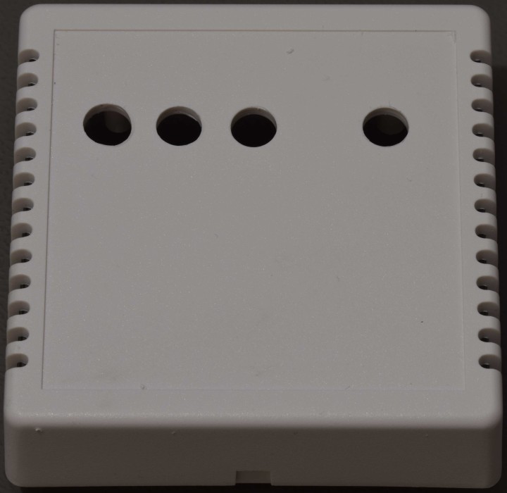
Use the front layout (see Project Elements for zipped BMP file) as a template for the correct position of the 4 holes, little marks are added in the center of the circles on the sticker. Be very careful when drilling in plastic enclosures. If drilling is done too fast or at first a too large drill size is used, the drill can “bite” and instead of a nice round hole there’s an ugly gap in it. So, to avoid this from happening mount the top side of the enclosure in a drill press vice and use a drill press (don't drill out of hand). First drill with a smaller drill then needed, e.g. 2.5 mm for the LED’s and slowly increase drill size for the correct size for the LED housings. Drilling 12 mm inside plastic takes experience, if done move the drill slowly in small steps up and down and remove chips regularly (the little strips of plastic that come of the drill). Give the chips a chance to clear the hole, but never touch the drill when it’s rotating!!! If the chips are not removed while drilling, these pieces can make the drill easily “bite” because the plastic is soft. The hole for the switch can be made by using a smaller drill, for instance 9 or 10 mm, first and then use a half-round file to increase the hole size to perfectly fit the switch. Drilling with 12 mm in soft plastic takes experience and if the drill bytes the rather large gap in the edge of the hole can be the result. Or, mark the 12 mm circle for the switch on the enclosure and use a small drill to make a kind of perforation inside the circle. Push out the center and file the rough edge to the 12 mm marked circle. Be careful, it’s plastic and filing takes little effort, not to say can be too easy. So always check size and position regularly, take your time and use little force then. When handling the top halve take good care not breaking the four plastic pins that secure the top halve in the bottom halve, no screws are used to hold them together. When drilling in the top place a piece of wood that will fit inside the top to prevent it from bending when pushing the drill through it.
USB connection
A notch must be made in one side of the bottom half of the enclosure to connect a 5 V USB DC adapter to the D1 mini module, which serves as the power supply for the CO2-Guard. For an an ordinary connector to fit the notch must be big enough to fit the full size of the connector, otherwise the connector can't be pushed through far enough. There are cables with an extended/longer metal part of the USB connector, then the notch can be made smaller. Place the D1 mini module on the PCB to mark the correct place for the notch. No need to solder the module with the accompanying male headers to the PCB yet. With the module placed on the PCB and the PCB placed correctly on the screw fixings, maybe use 2 screws temporarily, the position of the notch can be marked, it’s slightly of center.
Fan
No holes have to be made for the fan, it’s glued to the bottom side using super glue or epoxy adhesive. To avoid resonance the fan should not touch the top half of the enclosure. The fan should blow air out of the enclosure, before mounting it check the direction of the airflow by connecting it to a 3.3…5 V power supply. Pay close attention to polarity, wrong polarity may or will damage the fan (modern ones often have a small circuit inside). There’s probably a small header connected to the wires of the fan. Remove it (simply cut it and strip the ends of the two wires). The wires of the fan can be shortened since the connector on the PCB is right next to it. Preferably solder the wires directly to the header on the PCB (a socket can of coarse also be used, but there’ always a chance it will get loose over time).
LEDs
To connect the LED's only four wires are needed. Ground connection from the PCB to three LED's on the front can be one common connection. Connect the three cathodes of the LED's to use a single wire. Only a 5-pin header is needed on the PCB then.
PCB
All parts are through hole and the PCB is single sided, which makes removing parts relatively easy. A simple manual desoldering pump works fine if ever needed, since there are no metalized holes. But the number of parts is low and a mistake is not likely. Start mounting the lowest parts first. Start with the resistors and then diode, capacitors, transistor, buzzer and headers (sockets for the sensor MOD1, male headers for the switch, LED's and fan). Before you do this you can mount the D1 mini module (after programming it) but not MOD1 yet (the sensor module itself). To mount the D1 mini module (MOD2) first solder the two 8-pin male headers to the side of the module where the USB connector is located (see photo's below). We advise not use sockets on the PCB for MOD2 here. Since there’s some force on the module when plugging and unplugging the USB connector it’s best to solder the D1 mini onto the PCB. Also, on sockets it will limit airflow through the ventilation holes of the enclosure somewhat.
When the PCB is fixed with four screws to the bottom half of the enclosure and the fan glued the sensor module can be attached to the corresponding sockets.Never touch the top of the sensor, from the datasheet: Please avoid the pressure of its gilded plastic chamber from any direction, during welding, installation, and use. Especially never touch the air intake (white dust filter).
The 4-pin and 5 pin socket for the sensor probably come as one 10-pin SIL socket. Cut the 5th pin in half to get a separate 4 and 5-pin pin socket. Trying to break them usually happens in the middle of a pin anyway.
Also, a single 12-pin male SIL header must be separated into a 3-, 4- and 5-pin header for the fan switch/LED and the three LED’s.
Of coarse feel free to create your own front design. You can use a separate blue LED and switch for instance. But be aware of placement of the LED’s and switch, so they don’t come to close to the modules. Size of the area on the enclosure is 70.2 mm square.
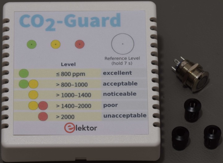
Photos: getting PCB and enclosure ready Top half of enclosure with paper copy of sticker on it to mark the place for the holes, led housings and switch next to it.
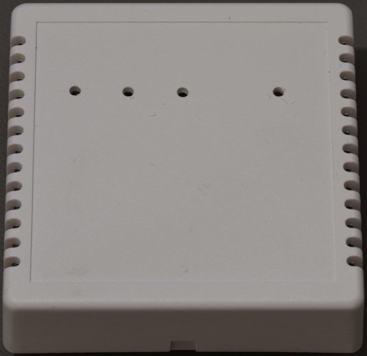 4 holes with 2.5 mm drill
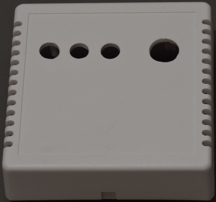
4 holes with 8 mm drill. The three holes for the led housings are finished.
The hole of the switch is enlarged to the correct diameter using a round file. Took about a minute, so be careful not to file too much!
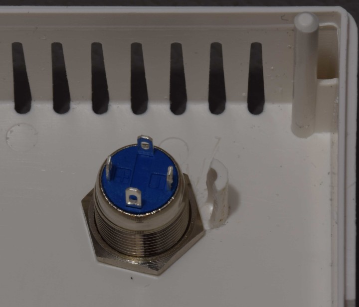
Removed part of a stand-off on the top half of the enclosure so the nut of the switch can be placed to secure the switch to the front.
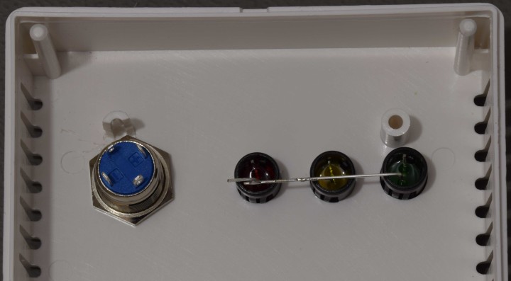
LED housings with LED's and switch mounted.
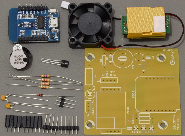
Overview of PCB, all parts of our prototype that are to be placed on it and the fan.
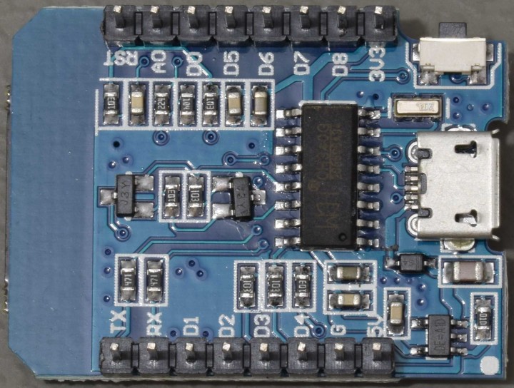
Solder the two 8-pin male headers to the D1 mini module
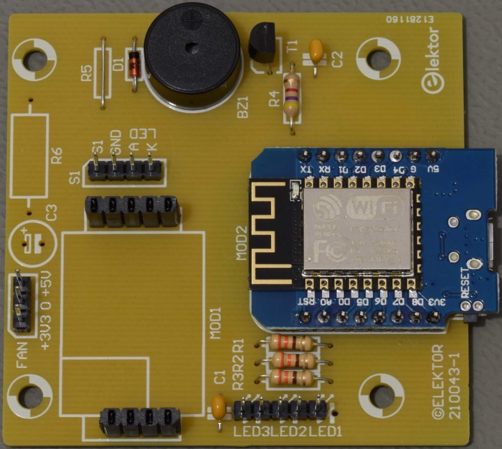
Solder the D1 mini module to the PCB after all other components are mounted.
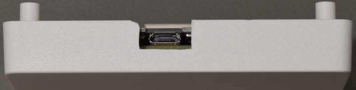
Opening for a standard size micro-USB connector, view from the side. A small sharp knife was used. Don’t use too much force or the knife may slip and cut too much. A tiny bit of one side was chipped off. And always cut away from your fingers!!!
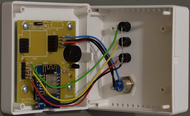
Place the top of the enclosure as close as possible to the bottom part. Connect LED's and the switch. Keep cable length to an absolute minimum. Here the 4 wires for the LED's are 12 cm long, the wires for the switch are 8.5 cm long. In a final version consider using heat shrink tubes to insulate the solder joints. Make sure when the enclosure is closed no wires are interfering with the antenna on the D1 mini module!
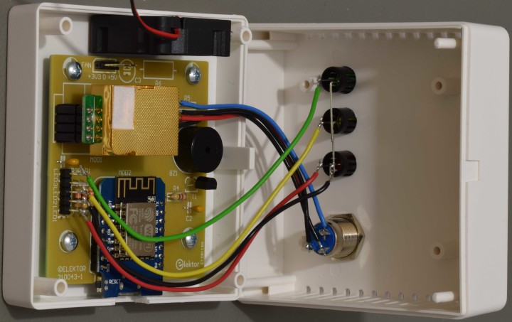
The fan can be glued to the bottom before putting the top on the enclosure. Don't forget to solder the wires of the fan to the connector next to it. Place the CO2 sensor. Do not put pressure on the gilded plastic chamber! Hold the sensor at the edges where the pins are to press the sensor into the sockets on the PCB.
Testing WiFi. When connected to your router the blue led of the switch should light.
Install Arduino IDE (do this before mounting the D1 mini on the PCB)
Download from here: https://www.arduino.cc/en/software, and save the file to a preferred location on your computer. Double click on the executable file and follow the instructions. Always click on ‘Install’ if asked for installing device software. Click on ‘Close’ when ‘Arduino Setup: Completed’ appears.
The D1 mini module uses a USB controller chip (CH340) which is not automatically recognized by Windows 10. If the CH340 IC is not recognized download the driver from the manufacturers website, here: http://www.wch-ic.com/downloads/CH341SER_EXE.html and download the file CH341SER.ZIP for Windows. Extract the zip file to a subfolder and run setup.exe and click on INSTALL. Close the window and connect the D1 mini module to your computer using a micro-USB cable
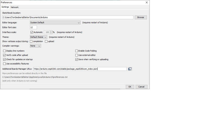
Start Arduino. Under menu File open Preferences and in Additional Boards Manager URLs enter:
https://arduino.esp8266.com/stable/package_esp8266com_index.json
Close this window with OK.
Open Tools – Board:…. and click on Boards Manager
In the entry field type esp8266
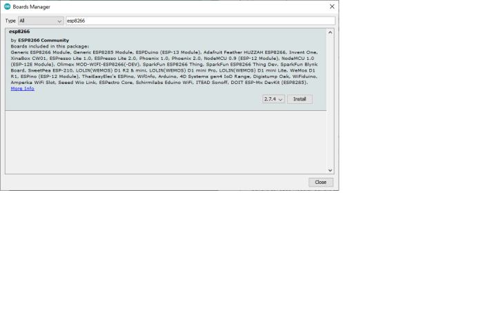
A version is displayed, the CO2-Guard was tested with 2.7.4. Click on ‘Install’. When finished installing click on ‘Close’.
In menu tools - Board: ...select in menu item ‘ESP8266 Boards (2.7.4)’ the board ‘LOLIN(WEMOS) D1 R2 & mini’. In menu ‘Tools’ following information should be visible.
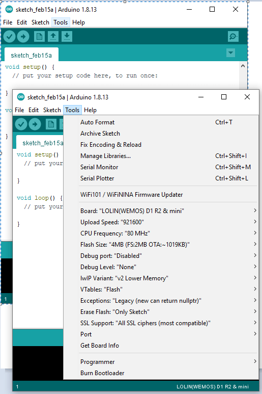
In menu Tools submenu Port select the COM port of the CH340 in de Device Manager (in our case it’s COM4). Close Arduino.
Upload program code
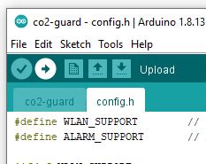
Download the file 210043-11.zip containing the Arduino sketch co2-guard.ino and file config.h and extract them to a subdirectory. Double click on co2-guard.ino, Arduino should open with the co2-guard sketch.
To compile and upload the code to the D1 mini click on the menu symbol for upload (arrow pointing to the right in the upper left corner.
ThingSpeak (create MathWorks account)
Visit the site: https://thingspeak.com/
Choose ‘Get Started For Free’. On the next page you have to create a MathWorks account (if you don’t already have one). Follow the instructions.
Or go to https://www.mathworks.com/mwaccount/register first.
After this create new channel (https://thingspeak.com/channels/new).

Enter the required data:
Name CO2_Guard
Description Monitor for CO2 levels with optical indication and acoustic alarm. Remote reading of CO2 level and temperature of sensor.
Field1 CO2
Field2 Temp
Tags CO2
Click on ‘Save Channel’
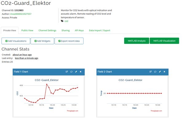
Now an overview of the channel just created is shown :
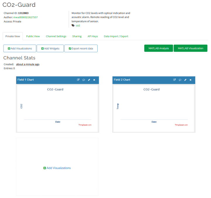
Now look under tab ‘API Keys’ and copy the Write API Key for later use. Keep it private and don’t show it to anyone else. Enter the Write API Key in the the config.h. Upload the software to the D1 mini and go to your ThingSpeak Account. Under menu Channels choose My Channels and then the tab Privat View. It should show something like this:
You can add individual users or make the channel public. That’s up to you. Individual users will get an email to the email address you entered under the tab Sharing (choice ‘Share channel view only with the following users:’):
Hi,
The ThingSpeak user, mwa……, has shared their ThingSpeak channel with you.
In order to view the channel, you will need to: Log in to www.ThingSpeak.com with the email address *** your email address*** and the password to your ThingSpeak account. If you do not have a ThingSpeak account with this email address, you may: Create a ThingSpeak account for free, or Request the author of the channel to share the channel with the email address listed on your ThingSpeak profile.Select the 'Channels Shared With Me' menu item from the 'Channels' menu in order to view this and other channels shared privately with you.Learn more or explore public channels on ThingSpeak to see examples of how other users use our service. Thank you,
The ThingSpeak Team
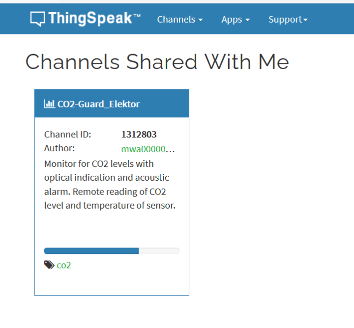
If someone shared a channel with you there’s a choice ‘Channels Shared With Me’ in your account:
Software
At power-up the three LED's should blink simultaneously for a while and then the green LED and blue LED of the switch should light, when CO2 level is lower than 800 ppm. In the file config.h the SSID and password of your router must be entered to get a working Wi-Fi connection. Important: the software downloaded from our website uses dummy values. From that config.h:
#ifdef WLAN_SUPPORT
const char* ssid = "abc"; // enter your own SSID of Router
const char* password = "abc"; // enter your own WiFi password
String APIKey = "123"; // enter your own API-Key Thing Speak
#endif
Also the Write API Key has to be entered here. Replace the text string between “ “.
Important
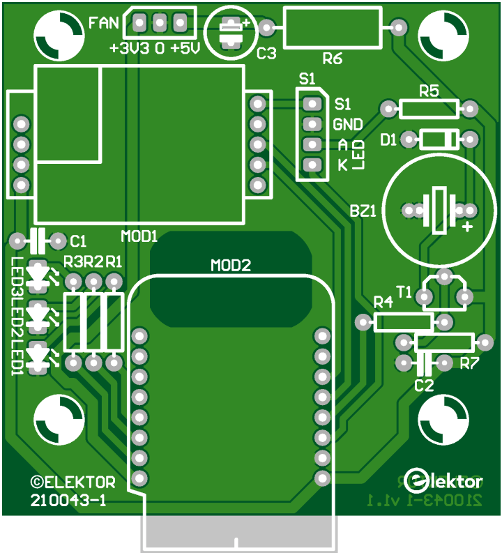
Do not short circuit the 5 V output of a clone of the D1 mini, a diode in series with the 5 V from the USB, serving as a protection against an externally connected 5 V source, will most likely burn out and both 5V and 3.3 V are missing then (our experience). A fuse like on the Wemos version is missing here. Replace the diode or solder a small wire across it (remove the damaged diode first), but it won’t always help. Ports used by the circuit can be damaged. Some I/O’s of the ESP8266 can become unresponsive if not all of them. We found out the hard way. Although, in this specific case uploading software to the D1 mini board could still be done without a problem. Even flashing the firmware of the ESP8266EX chip can be done without errors but in our case didn’t help getting all I/O’s working again. Best is to replace the D1 mini then.Top overlay (copper bottom shown) of the single sided PCB of the CO2-Guard (210043-1 v1.1)
Bill of material CO2-Guard 210043-1 v1.1
| Resistor
| R1,R2,R3 = 330 Ω, 0.25 W, 5 %
| R4 = 4.7 kΩ, 0.25 W, 5 %
| R5 = 0 Ω, place wire, see text for more info
| R6 = 0 Ω, place wire for 5V or leave open, see text about value
| R7 = 1.5 kΩ, 0.25 W, 5 %
|
Capacitor
| C1,C2 = 100 nF, 50 V, 10 %, X7R, lead spacing 5 mm
| C3 = 100 µF, 25V, optional , not mounted, see text
|
| Semiconductor
| D1 = BAT85, DO-35
| T1 = BC327, PNP, TO-92
| LED1 = LED red, 5 mm
| LED2 = LED yellow, 5 mm
| LED3 = LED green, 5 mm
|
| Other
| MOD1 = 1x10 SIL header, female, split in 1x4 and 1x5 (*1)
| MOD1 = MH-Z19C, version 400-5000ppm, pins on bottom
| MOD2 = Wemos D1 mini
| MOD2 = 2 1x8 SIL header, male , 2 are part of D1 mini package
| S1 = switch+build-in LED (momentary on, self-reset, blue circle)
| Enclosure PP73BL, Supertronic
| BZ1 = DC buzzer, 5V, pitch 5 or 7.62 mm, diam. 14 mm max
| heat shrink tube, I.D 2.4 mm, 20 cm
| led housing, for 5 mm LED (LED1..3), Black
| FAN 5 VDC, 30x30x10.5 mm
| 12-pin male SIL header (separate in 3, 4, 5pens)
thin stranded wire to connect LED's and switch:
| stranded wire, 0.25 mm2, black, (2x8.5+12cm)
| stranded wire, 0.25 mm2, red, (8.5+12cm)
| stranded wire, 0.25 mm2, yellow, (12cm)
| stranded wire, 0.25 mm2, green, (12cm)
| stranded wire, 0.25 mm2, blue, (8.5cm)
|
Misc.
| PCB 210043-1 v1.1
KiCad Project
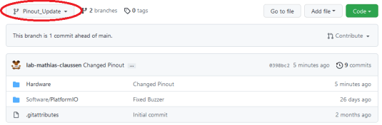
While the Projet is done in Altium, Mathias Claußen has already posted his progess on moving the design into KiCad.
While the project has been build and also PCBs have been ordered, please consider the KiCad project not as perfect and it is included for you to expore the PCB and also able to order it from a service you preffer. Also note that a Branch "Pinout_Update" now exists with an untested PCB. As I²C is not working with the remaining Pins the configuration has been swapped and a header for I²C is installed on this PCB revision.
D1/D2 (I²C) connected to pinheader
D3/D4 RX/TX Sensor
D0 LED R
D7 LED G
D6 LED Y
D5 LED C
D8 Buzze
This shoudl allow for own I²C addons (e.g BME280 / BMP280 ) and sensors. Use this PCB at your own risk. It has not been tested.
Projectfiles can be found on GitHub

Want to build a project?
Bring your design to life with the Elektor PCB Service, powered by Eurocircuits. Upload the project files and order professionally manufactured PCBs or assembled boards through a proven European production platform.
Supporting KiCad, Eagle, Gerber, and ODB++ formats, the service is suitable for everything from prototypes and validation builds to series production and volume manufacturing.
Made in Europe. Fast. Reliable. Professional.
Discussie (9 opmerking(en))