
Dual Geiger-Müller Tube Radiation Sensor for Arduino
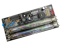
High sensitivity, very low power radiation sensor in a Arduino shield form factor.
Like many other hobbyist I have always been fascinated by radioactivity and the sensors to detect it.Geiger-Müller tubes are a common and relatively inexpensive way to measure radiation. GRAD is a complete solution for radiation counting in an Arduino shield form factor. Its main features are dual tube support to increase sensitivity and very low power consumption
Introduction to Geiger-Müller Counters
Every Geiger-Müller counter requires 4 essential functional blocks.
Schematics
There are many circuits on the web for Geiger-Müller tube power supplies. Many are boost converters built around the 555 timer, some open loop, some with feedback. The open loop designs were not considered as they require tuning per board and do not provide a stable voltage at high pulse counts.Closed loop design are more suitable as they provide the required stability. However, to keep overall power consumption low, special attention should be paid to the feedback loop (12uA of current @ 400V is ~5mW).
To avoid the power penalty of high voltage feedback, the most elegant solutions use a non isolated step-up transformer and detect the voltage on the primary side like the Analog Devices LT3420.
We implemented a simple switch mode boost converter with a very low current feedback. Our design is heavily based on the Theremino Geiger adapter. We mixed the SMD, DIY and "Flintstones" versions in a fully PTH design with Zener diode feedback.
The Schmitt trigger inverter U1C, R4 and C5 form a oscillator that generates the pulses to drive the main switch Q2. U1A, U1B and U1D are in parallel to increase Q2 base current.
The feedback is implemented with a series of very low leakage current Zener diodes. When the output voltage exceeds the Zener voltage Q1 turns on and stops the oscillator. When the output voltage drops again Q1 will turn off releasing the oscillator. R1 and C3 further reduce the output ripple. Additional series resistors feed each tube separately (R2 and R3 for GM1, R13 and R14 for GM2).
Pulses are picked up from the high voltage side of the tube using a DC blocking capacitor (C6 and C7). The pulses are shaped by the remaining Schmitt trigger inverters.
J1-J4 are the standard Arduino connectors. GRAD only uses a few pins..
D2 and D3 were chosen as they are interrupt pins on the Arduino UNO. This allow the Arduino to count pulses in the background while it is performing other actions.
Arduino pins D8 and D9 are connected to a pair of LEDs to visually show when a ionizing radiation hits the respective tube. Pin D4 is connected to a piezo speaker to provide audible feedback.
Finally D5 is connected to a low pass filter formed by R20, R21 and C20 to connect a simple analog meter.
Tube options
The board is designed to work with 105mm Soviet SBM-20, STS-5 and the Chinese J305 or the 90mm J305 and M4011.
Any other 400V tube will also work with some customized tube mounting. In case of custom mounting, to minimize parasitic capacitance, it is important to keep the positive wire as short as possible.
For tubes requiring different voltages, the Zener diode(s) should be changed to obtain the required voltage. Any diode with 0.5uA or less of leakage should work.
Performance
The power supply consumes 325uW (65uA) at 5V, In battery operated devices the board can also be powered with 3.3V. At the lower voltage the power drops to 150uW (45uA).
Arduino Sample Code
A simple Arduino sketch to drive the counter is available in the files section below. Every 60 seconds, the software will output a csv row with a sequential number, raw count for each tube, a moving average of cnt1+cnt2 and a uSv/h dose rate based on the average count. The attached chart shows the background radiation in Santa Clara, CA measured using GRAD with two SBM-20 tubes
There are a few defines at the beginning that are configurable to match the board configuration and/or user preferences. The first set configures the Geiger-Müller tube parameters and the moving window size for the reporting.
The CPM2USV parameter is the count per minute for 1uSv/h for your particular tube. Unfortunately there is no published "correct" number for this parameter. For the SBM-20 radiation enthusiasts on the web use values that range from 130 to 220 (conversion factor of 0.0075 to 0.0045).
The TUBES parameter, as the name states, defines the number of tubes installed. Valid values are 1 and 2.
Finally the WSIZE define the moving average window size for the counts. The default value of 10 defines a 10 minute window.
The second set of parameters defines how the optional hardware functions are connected:
All three *_PIN defines select the Arduino pin where the LED or the speaker are connected. To avoid damaging the Arduino, make sure to add a suitable series resistor between the pin and the LED or the speaker.
The LED_BLINK_MS defines the time that the led will stay on for each count that the tube receives.
LoRaWAN Networking
The basic sketch requires the unit to be tethered to a computer through USB. Often is desirable to place the sensor far from the computer where a USB connection is not available.
A Dragino LoRa shield can be stacked to enable LoRa connectivity. Unfortunately, the Dragino shield also uses Arduino pin 2, so there are 2 options
Single tube option
In this case only tube 2 can be used.and pin 10 of U1 must be disconnected to prevent interference with the LoRa communication. The attached pictures show the full stack with a single soviet SBM-19.
Two tube option
in this case both the Dragino shield and the GRAD board must be modified.
For the Dragino shield R5 and Jxx must be removed. A wire should be used to connect the radio DIO0 to arduino D7.
For the GRAD board R7, R12, C20 and the two LEDs should be removed. R21 should be substituted with a short. and a single led should be placed at the J9 site (replace the analog meter output).
A sketch that communicates to the TTN and posts tube counts every 60 seconds is being worked on. A simple node-red flow is used to display the data.
Measuring Radiation
To verify the correct function of the Geiger counter a radiation source is required. These can be purchased online from specialty suppliers. Alternatively specific vintage items that were built using small quantities of radioactive materials can be purchased at a thrift store or ebay. Common radioactive items include: uranium glass items, thorium lantern mantles and selected colors of vintage fiestaware items.
Lacking any of these another simple way is to check the decay product of Radon captured by the air filter from an air conditioner or an air purifier. These have a relatively short half life (in the order of tens of minutes) so make sure you run the AC for a couple of hours and then measure the filter immediately. If the filter is fine enough to it will emit radiations at a rate many time higher than background in your area. The chart below shows the count reaching almost ten times the background and then following the exponential curve typical of radioactive decay.
Kits on Elektor Store
The kits on the Elektor store contain A05 PCBs. These have an identical circuit to the published A03. The only difference is the addition of alternate footprints for several components (the geiger tubes, the speaker and a few passive components). I included the new schematics to the project for completeness.
Due to the component shortage in 2022 some of the kits have shipped with two 200V Zeners (D2, D3) instead of four 100V diodes (D2, D3, D4, D5). In this case a wire jumper should be used for D3 and D4.
Assembly
The recommended order of assembly is: solder all resistors, then the diodes (except the LEDS).
If your Kit contains only two zeners, place them in D2 and D3 and use a wire jumper for D4 and D5.
The IC socket and the ceramic capacitors are next. Then the polarized caps making sure the polarity matches the silkscreen on the PCB, inductor, transistors and speaker.
When there are two footprint for a component, make sure to insert the component to the correct hole pattern to prevent damage to the component terminals.
Finish up with the LEDs and all connectors. For the tube clips make sure to select the correct location that matches your tube. For the shipping J305 the middle location is the correct one.
Insert the IC into the socket and the tubes(s) into the clips.
Upload the sketch to test. Depending on your location you should get a background count of 10-20cpm, per tube even without any radioactive source.
Introduction to Geiger-Müller Counters
Every Geiger-Müller counter requires 4 essential functional blocks.
- Geiger-Müller Tube. The tube has two terminals and is filled with a low pressure gas mixture. When biased with the appropriate voltage the gas will ionize and briefly conduct electricity every time it is hit by radiation. Depending on the tube type it is possible to detect alpha, beta and gamma particles. The SBM-20 used in the GRAD is sensitive to gamma and high energy beta.
- High Voltage Power Supply. The tube must be operated in the Geiger Plateau. This is a region where the pulse count is almost independent of the bias voltage. For common tubes the bias voltage is between 400 and 500V. The SBM-20 optimal point is around 400V.
- Pulse Detector. The pulses out of the tube are very short and variable voltage. The pulse detector conditions the signal so it can be easily counted by the following stage
- Pulse counting. Pulses are counted over a fixed amount of time to calculate a CPS (counts per second) or CPM (counts per minute) value. This can be roughly converted to a dose rate by using the parameter on the tube datasheet. Arduino is used for pulse counting and its visualization and/or logging.
Schematics
There are many circuits on the web for Geiger-Müller tube power supplies. Many are boost converters built around the 555 timer, some open loop, some with feedback. The open loop designs were not considered as they require tuning per board and do not provide a stable voltage at high pulse counts.Closed loop design are more suitable as they provide the required stability. However, to keep overall power consumption low, special attention should be paid to the feedback loop (12uA of current @ 400V is ~5mW).
To avoid the power penalty of high voltage feedback, the most elegant solutions use a non isolated step-up transformer and detect the voltage on the primary side like the Analog Devices LT3420.
We implemented a simple switch mode boost converter with a very low current feedback. Our design is heavily based on the Theremino Geiger adapter. We mixed the SMD, DIY and "Flintstones" versions in a fully PTH design with Zener diode feedback.
The Schmitt trigger inverter U1C, R4 and C5 form a oscillator that generates the pulses to drive the main switch Q2. U1A, U1B and U1D are in parallel to increase Q2 base current.
The feedback is implemented with a series of very low leakage current Zener diodes. When the output voltage exceeds the Zener voltage Q1 turns on and stops the oscillator. When the output voltage drops again Q1 will turn off releasing the oscillator. R1 and C3 further reduce the output ripple. Additional series resistors feed each tube separately (R2 and R3 for GM1, R13 and R14 for GM2).
Pulses are picked up from the high voltage side of the tube using a DC blocking capacitor (C6 and C7). The pulses are shaped by the remaining Schmitt trigger inverters.
J1-J4 are the standard Arduino connectors. GRAD only uses a few pins..
D2 and D3 were chosen as they are interrupt pins on the Arduino UNO. This allow the Arduino to count pulses in the background while it is performing other actions.
Arduino pins D8 and D9 are connected to a pair of LEDs to visually show when a ionizing radiation hits the respective tube. Pin D4 is connected to a piezo speaker to provide audible feedback.
Finally D5 is connected to a low pass filter formed by R20, R21 and C20 to connect a simple analog meter.
Tube options
The board is designed to work with 105mm Soviet SBM-20, STS-5 and the Chinese J305 or the 90mm J305 and M4011.
Any other 400V tube will also work with some customized tube mounting. In case of custom mounting, to minimize parasitic capacitance, it is important to keep the positive wire as short as possible.
For tubes requiring different voltages, the Zener diode(s) should be changed to obtain the required voltage. Any diode with 0.5uA or less of leakage should work.
Performance
The power supply consumes 325uW (65uA) at 5V, In battery operated devices the board can also be powered with 3.3V. At the lower voltage the power drops to 150uW (45uA).
Arduino Sample Code
A simple Arduino sketch to drive the counter is available in the files section below. Every 60 seconds, the software will output a csv row with a sequential number, raw count for each tube, a moving average of cnt1+cnt2 and a uSv/h dose rate based on the average count. The attached chart shows the background radiation in Santa Clara, CA measured using GRAD with two SBM-20 tubes
Seq , cnt1 , cnt2 , avg10 , uSv/h
1 , 14 , 19 , 33.0 , 0.075
2 , 10 , 17 , 32.3 , 0.073
3 , 16 , 12 , 31.8 , 0.072
4 , 16 , 24 , 32.5 , 0.074
5 , 13 , 11 , 31.6 , 0.072
There are a few defines at the beginning that are configurable to match the board configuration and/or user preferences. The first set configures the Geiger-Müller tube parameters and the moving window size for the reporting.
#define CPM2USV 220     // tube CPM to uSv/h conversion factor
#define TUBES 2         // number of tubes installed
#define WSIZE 10        // moving average window (in minutes)
The CPM2USV parameter is the count per minute for 1uSv/h for your particular tube. Unfortunately there is no published "correct" number for this parameter. For the SBM-20 radiation enthusiasts on the web use values that range from 130 to 220 (conversion factor of 0.0075 to 0.0045).
The TUBES parameter, as the name states, defines the number of tubes installed. Valid values are 1 and 2.
Finally the WSIZE define the moving average window size for the counts. The default value of 10 defines a 10 minute window.
The second set of parameters defines how the optional hardware functions are connected:
#define LED1_PIN     8  // pin for TUBE1 LED
#define LED2_PIN     9  // pin for TUBE2 LED
#define SPKR_PIN     4  // pin for speaker connection
#define LED_BLINK_MS 20 // duration of LED blink for each count
All three *_PIN defines select the Arduino pin where the LED or the speaker are connected. To avoid damaging the Arduino, make sure to add a suitable series resistor between the pin and the LED or the speaker.
The LED_BLINK_MS defines the time that the led will stay on for each count that the tube receives.
LoRaWAN Networking
The basic sketch requires the unit to be tethered to a computer through USB. Often is desirable to place the sensor far from the computer where a USB connection is not available.
A Dragino LoRa shield can be stacked to enable LoRa connectivity. Unfortunately, the Dragino shield also uses Arduino pin 2, so there are 2 options
Single tube option
In this case only tube 2 can be used.and pin 10 of U1 must be disconnected to prevent interference with the LoRa communication. The attached pictures show the full stack with a single soviet SBM-19.
Two tube option
in this case both the Dragino shield and the GRAD board must be modified.
For the Dragino shield R5 and Jxx must be removed. A wire should be used to connect the radio DIO0 to arduino D7.
For the GRAD board R7, R12, C20 and the two LEDs should be removed. R21 should be substituted with a short. and a single led should be placed at the J9 site (replace the analog meter output).
A sketch that communicates to the TTN and posts tube counts every 60 seconds is being worked on. A simple node-red flow is used to display the data.
Measuring Radiation
To verify the correct function of the Geiger counter a radiation source is required. These can be purchased online from specialty suppliers. Alternatively specific vintage items that were built using small quantities of radioactive materials can be purchased at a thrift store or ebay. Common radioactive items include: uranium glass items, thorium lantern mantles and selected colors of vintage fiestaware items.
Lacking any of these another simple way is to check the decay product of Radon captured by the air filter from an air conditioner or an air purifier. These have a relatively short half life (in the order of tens of minutes) so make sure you run the AC for a couple of hours and then measure the filter immediately. If the filter is fine enough to it will emit radiations at a rate many time higher than background in your area. The chart below shows the count reaching almost ten times the background and then following the exponential curve typical of radioactive decay.
Kits on Elektor Store
The kits on the Elektor store contain A05 PCBs. These have an identical circuit to the published A03. The only difference is the addition of alternate footprints for several components (the geiger tubes, the speaker and a few passive components). I included the new schematics to the project for completeness.
Due to the component shortage in 2022 some of the kits have shipped with two 200V Zeners (D2, D3) instead of four 100V diodes (D2, D3, D4, D5). In this case a wire jumper should be used for D3 and D4.
Assembly
The recommended order of assembly is: solder all resistors, then the diodes (except the LEDS).
If your Kit contains only two zeners, place them in D2 and D3 and use a wire jumper for D4 and D5.
The IC socket and the ceramic capacitors are next. Then the polarized caps making sure the polarity matches the silkscreen on the PCB, inductor, transistors and speaker.
When there are two footprint for a component, make sure to insert the component to the correct hole pattern to prevent damage to the component terminals.
Finish up with the LEDs and all connectors. For the tube clips make sure to select the correct location that matches your tube. For the shipping J305 the middle location is the correct one.
Insert the IC into the socket and the tubes(s) into the clips.
Upload the sketch to test. Depending on your location you should get a background count of 10-20cpm, per tube even without any radioactive source.
Updates van de auteur