
True Random Number Generator
Mixing three of my favorite electronics/physics topics: clocks, crystal oscillators, and ionizing radiation; to create a True Random Number Generator.
Random numbers are used in fields such as data encryption and scientific research. In some applications, it is OK to use “pseudo-random” numbers, which are generated by a deterministic algorithm (usually in software). But the output of an algorithm can be reversed, and a pseudo-random sequence will eventually repeat itself. So, there are some applications where a “true random number” is required. A true random number can be generated by basing it on a natural event that simply cannot be predicted as to its time and/or magnitude. One such type of event is nuclear decay.
This device includes a 32-bit counter running at 48 Mhz (a timer peripheral inside the MCU), and the counter is halted by a nuclear decay event from a Geiger tube. Since the timing of the nuclear event is completely unpredictable, the value of the counter is truly random.
The device is also a clock. I enjoy making clocks because they are doing something useful all day, every day – other types of projects may sit on the shelf, not being used… The unique feature of this clock is that the time base is made with old and unusual components. The crystal is from a military radio transmitter, and dates from before 1950. The oscillator circuit uses a DTL logic gate IC that was made in 1971. DTL devices have been obsolete for about 45 years. This oscillator performs well – the clock is accurate to within 3 or 4 seconds per month.
Hardware Features
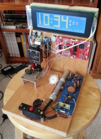
Refer to the attached picture “GeigerClock_numbered”:
1 – The MCU board, a Texas Instruments MSP-EXP432P401R.
2 – A graphical LCD display. It has an 8-bit parallel data interface, plus 4 control signals.
3 – A HV power supply for the CCFL backlight for the LCD display.
4 – A DC-DC regulator to create 5V for various other circuits. The input to this regulator is 18VDC, from an old laptop computer supply.
5 – An “FT-171-B” crystal, marked “2145 KC”. It was made to be used in a military BC-610 transmitter. It has male banana plugs, and the pin spacing (3/4 inch) is the same as found on many types of old test equipment.
6 – The crystal oscillator circuit, featuring an MC857 quad NAND gate, made in 1971. See the “xtal_osc_MC857” picture. The circuit works with crystals up to about 4 Mhz. The first two gates form the oscillator, the third gate buffers the output, and the fourth gate is unused. The IC operates from 5V, but the output is clamped to 3.3V by the base-emitter junction of an old 2N1304 transistor, so that the signal can be connected directly to the MSP432 MCU.
7 – The HV power supply for driving the Geiger tube. It outputs about 650 volts, at a very low current. It is switched on and off by a GPIO from the MCU. See the “Geiger_PS_SCH” picture. The first 555 timer outputs a series of pulses, and drives a high-voltage MOSFET. The MOSFET and the inductor and diode form a flyback supply, which then drives a voltage doubler. A negative pulse from the Geiger tube is buffered by the 2N3904, which triggers a one-shot pulse from the second 555 timer. The output is taken from the anode of the blue LED, which can be connected directly to the MCU, because the forward voltage of the LED is close to 3.3V (this output connection is not shown in the old hand-drawn schematic – I originally built this PS module about 12 years ago).
8 – Inside this aluminum housing is a type 5980 Geiger tube, made in the 1960’s. An output pulse from the Geiger tube drives an interrupt input to the MCU.
9 – An old wrist watch, with a Radium dial. The Radium is detected by the Geiger tube, at a rate of about 2 events per second (average). Without this source of radiation near the tube, it would be necessary to wait for ‘background radiation’ to trigger an event, but this could require 20 or 30 seconds. The wrist watch no longer runs, but the Radium will keep “running” for about 1600 years!
10 – This is the “Red Button”. Pushing the button causes the MCU to execute the process to generate and display a random number. See the “GeigerClock_2” picture. Only the lower 4 digits of the count are displayed, but the higher digits are skewed towards lower numbers, because the counter doesn’t have time to overflow between events.
This clock/TRNG sat outside my office last year, and many of my colleagues would stop by to get their “daily random number”.
The main portion of the source code is in “main.c”. If interested, I can post the entire set of project files, for TI’s “Code Composer Studio”.
Thanks for reading – any questions or comments are welcome!
This device includes a 32-bit counter running at 48 Mhz (a timer peripheral inside the MCU), and the counter is halted by a nuclear decay event from a Geiger tube. Since the timing of the nuclear event is completely unpredictable, the value of the counter is truly random.
The device is also a clock. I enjoy making clocks because they are doing something useful all day, every day – other types of projects may sit on the shelf, not being used… The unique feature of this clock is that the time base is made with old and unusual components. The crystal is from a military radio transmitter, and dates from before 1950. The oscillator circuit uses a DTL logic gate IC that was made in 1971. DTL devices have been obsolete for about 45 years. This oscillator performs well – the clock is accurate to within 3 or 4 seconds per month.
Hardware Features
Refer to the attached picture “GeigerClock_numbered”:
1 – The MCU board, a Texas Instruments MSP-EXP432P401R.
2 – A graphical LCD display. It has an 8-bit parallel data interface, plus 4 control signals.
3 – A HV power supply for the CCFL backlight for the LCD display.
4 – A DC-DC regulator to create 5V for various other circuits. The input to this regulator is 18VDC, from an old laptop computer supply.
5 – An “FT-171-B” crystal, marked “2145 KC”. It was made to be used in a military BC-610 transmitter. It has male banana plugs, and the pin spacing (3/4 inch) is the same as found on many types of old test equipment.
6 – The crystal oscillator circuit, featuring an MC857 quad NAND gate, made in 1971. See the “xtal_osc_MC857” picture. The circuit works with crystals up to about 4 Mhz. The first two gates form the oscillator, the third gate buffers the output, and the fourth gate is unused. The IC operates from 5V, but the output is clamped to 3.3V by the base-emitter junction of an old 2N1304 transistor, so that the signal can be connected directly to the MSP432 MCU.
7 – The HV power supply for driving the Geiger tube. It outputs about 650 volts, at a very low current. It is switched on and off by a GPIO from the MCU. See the “Geiger_PS_SCH” picture. The first 555 timer outputs a series of pulses, and drives a high-voltage MOSFET. The MOSFET and the inductor and diode form a flyback supply, which then drives a voltage doubler. A negative pulse from the Geiger tube is buffered by the 2N3904, which triggers a one-shot pulse from the second 555 timer. The output is taken from the anode of the blue LED, which can be connected directly to the MCU, because the forward voltage of the LED is close to 3.3V (this output connection is not shown in the old hand-drawn schematic – I originally built this PS module about 12 years ago).
8 – Inside this aluminum housing is a type 5980 Geiger tube, made in the 1960’s. An output pulse from the Geiger tube drives an interrupt input to the MCU.
9 – An old wrist watch, with a Radium dial. The Radium is detected by the Geiger tube, at a rate of about 2 events per second (average). Without this source of radiation near the tube, it would be necessary to wait for ‘background radiation’ to trigger an event, but this could require 20 or 30 seconds. The wrist watch no longer runs, but the Radium will keep “running” for about 1600 years!
10 – This is the “Red Button”. Pushing the button causes the MCU to execute the process to generate and display a random number. See the “GeigerClock_2” picture. Only the lower 4 digits of the count are displayed, but the higher digits are skewed towards lower numbers, because the counter doesn’t have time to overflow between events.
This clock/TRNG sat outside my office last year, and many of my colleagues would stop by to get their “daily random number”.
The main portion of the source code is in “main.c”. If interested, I can post the entire set of project files, for TI’s “Code Composer Studio”.
Thanks for reading – any questions or comments are welcome!
Discussie (0 opmerking(en))