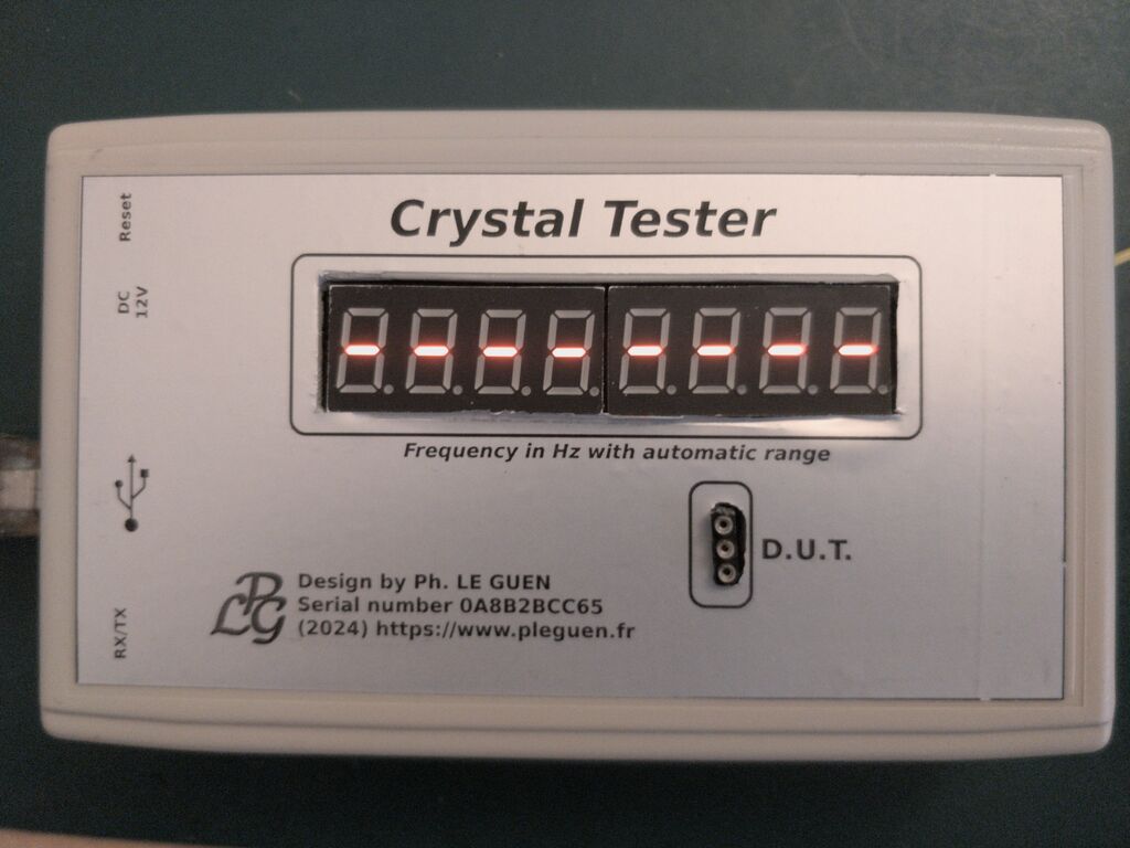
On this page I present to you a small instrument capable not only of checking the good condition of a crystal (sometimes unknown when its marking is erased or illegible...) but also of displaying its frequency.
Principle of operation
This little instrument of course does not claim to compete with more complex and more expensive professional instruments, but it can be useful when one finds oneself in the presence of an unknown crystal or even to check its proper functioning. It not only allows you to check the good condition of the component but also to display its frequency in 8 digits. The tolerance that I was able to measure on my copy is less than 1 ppm.
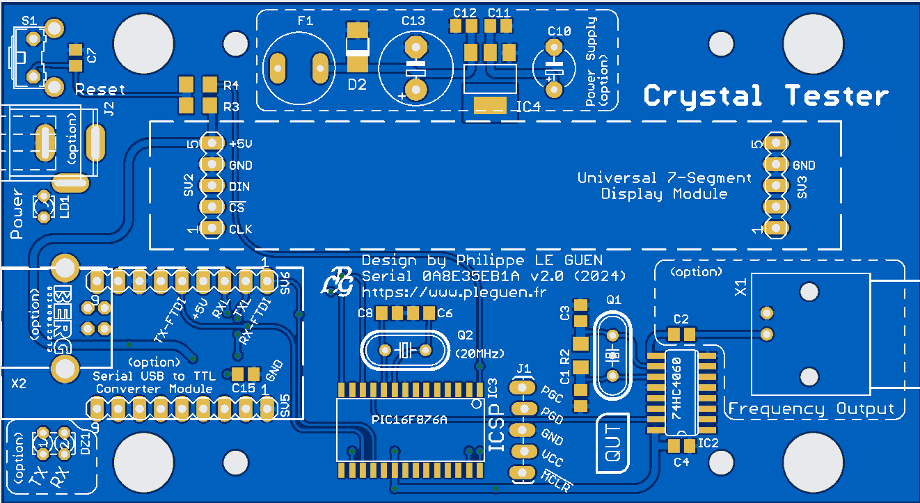
All the electronics are structured around a PIC16F876A microcontroller which counts the pulses coming from a 14-stage analog counting circuit (74HC4060) after dividing the frequency of the crystal to be analyzed by 1024. Why these choices?
I once again wanted to use recovery components that I have at the Lab
the 74HC4060 integrated with the RC cell composed of R2/C1/C1 and the crystal to be tested a Pierce oscillator, the resulting signal is available at pin 15 (Q9) after division ÷1024
the chosen microcontroller (this remains valid even for PIC18FXXXX) already uses its 1:256 predivisor and cannot count beyond 65535 in direct measurement (RC0/T1CKI). To be able to control crystals up to more than 30 MHz it becomes necessary to use an additional divider, by 1024 in this case and this is the reason for the presence of a 74HC4060. In 16-bit mode, Timer1 of the PIC16F876A cannot count beyond 65535. By using a 74HC4060 upstream with its Q9 output which counts up to 1024, it then becomes theoretically possible to measure frequencies of 67 MHz (65535 × 1024 = 67.10784e6) and it works, this was verified with my function generator. In fact and taking into account the tiny error generated by the system, I was not able to exceed the input frequency of 65.530 KHz (in pin 11/RC0 of IC3). The display then indicated 67,107,840 which divided by 1024 gives 65535, the maximum that Timer1 of the microcontroller can count. Taking into account the multiplier coefficient (1024) the resolution of the instrument is 1024 Hz. A variation in the frequency of the D.U.T. of 1 Hz causes a variation in the display of 1024 units.
A 74HC4040 could also be used with its Q9 output (÷1024) but the pinout of this component is different from the one I use and in this case it would be necessary to review the routing of the printed circuit.
The display part uses a small 8-digit 7-segment module (Arduino module available almost everywhere on the internet...) controlled via its SPI Bus, the processor being clocked by a 20 MHz crystal. I wrote the little software in microC language. Programming can be done with the programmer of your choice (mine is Microchip's PICkit4) via the ICSP connector. I have planned the installation of a bootloader which allows, with the USB-UART stage, to facilitate a possible modification and/or update of the code without needing to open the device or extract the microcontroller. A microswitch accessible through the box allows it to be reset during the programming process.
Power supply is possible via this USB interface or via an external DC12V source with the entire power supply regulated by +5V (optional). On my copy I noticed that when using an external power supply alone, the RX/TX LEDs were lit even without the presence of USB... the cause is that when using an external power supply, pin 20 (VCC ) of IC5 (FT232) does not receive the +5V necessary for its operation, pins 22 and 23 (CBUS0/CBUS1) being in the low state which causes the two LEDs to light up. If you don't mind their illumination you can leave diode D3 in place. In fact I drew the USB-UART interface part from the diagram of a 'Ready for PIC' card from mikroElektronika which I used during the development of this project without paying too much attention to this particularity, hence the presence of this diode intended to protect the +5V coming from the PC's USB when the external +12V is also connected to the card. The consumption of the card is around 40 mA with the 8 digits lit under +12V which remains reasonable (taking into account the reduction in brightness...), because during the test mode with all of the display on, the consumption increases to approximately 260 mA (the fuse must in this case be a model of at least 500 mA).
A BNC socket also optional can be used to view the signal measured on an oscilloscope, or to connect a frequency meter. The oscillator could have been made based on a Colpitts oscillator but I would still have needed a pre-divider before sending the resulting signal to the microcontroller. So the trick is to build this oscillator with the 74HC4060.
Software
The little software that I wrote in mikroC language and requires very little resources:
Used RAM (bytes): 37 (11%) Free RAM (bytes): 315 (89%)
Used ROM (program words): 1166 (14%) Free ROM (program words): 7026 (86%)
The principle is quite simple, the measurement frequency of the D.U.T. associated with the oscillator composed of IC2 (74HC4060) as well as the RC cell (R2/C1/C2) and divided ÷1024, the resulting signal being available at pin15 (Q9) of IC2. This signal is directly routed to microcontroller IC3 (PIC16F876A) at pin11 (RC0/T1CKI). A pulse counter using Timer1 counts these pulses over a duration of 1 second, and by multiplying the number of pulses by 1024, we then obtain the frequency of the crystal analyzed. The result is displayed on 8 digits 7-segment via a SPI serial bus. Mini/max detection is carried out for each new measurement generating an appropriate display:
eight dashes '--------' meaning that the frequency read is too low, this may be the case with a crystal of 32.768 KHz for example, because the chosen oscillator does not allow measurement. This can also indicate the absence of the component to be tested, or even its defect.
'0F. Error' (Overflow error) meaning that the frequency read is too high, the maximum being 67.10784e6 or approximately 67 MHz
Depending on the value of the frequency to be displayed, the thousands points are automatically positioned to make them easier to read. The microcontroller can be programmed with a BootLoader but this is not an absolute necessity. This simply allows for easier software updating via the UART-USB socket. The one I used is 'Tiny Bootloader' working perfectly under Windows10. This time I did not forget to provide an ICSP connector on the printed circuit to program the PIC. I no longer use strips or other connectors for this but simply provide the footprint of the five pads necessary during programming (MCLR/VCC/GND/PGD/PGC). These pads are not perfectly aligned but have a slight offset from each other, which provides good support as well as good contacts when connecting the programmer. To connect my PICkit4 I use a flexible cable of 5 conductors that I simply made.
Realization
Due to the construction that I chose, we are in the presence of a so-called double-decker assembly, the display module having to be soldered on top of the main circuit.
It should be noted that he is not the only one in this case since I also planned the same assembly method for the USB-UART module. I have some in the Lab but I preferred to use components recovered from old cards which I use as component donors. Thus the printed circuit has the locations provided for the two assembly modes, modular or with components in SMT technology. All the components in the diagram are not absolutely necessary (there is then the mention 'option'), you can very well not wire the USB-UART module but use an external power supply to use the machine, or not wire it the +5V regulation part and then use the USB-UART part with either the components mounted on the printed circuit, or use a small module (Arduino module available almost everywhere on the internet...). It will be according to your personal choices, I designed the circuit board accordingly. Check the compatibility of the module you are going to buy because it is possible that some pinouts are different from the one I have in the Lab...
One of the only difficulties lies in soldering the IC5 integrated circuit (FT232RL) because the pitch is really low (0.65 mm) and it is necessary to have a thermostatically controlled iron with a sufficiently fine tip, but this component remains an option which is not useful. only to the USB connection for possible software updates and is therefore not at all necessary if you do not program a BootLoader in the microcontroller.
Programming
I refer you to a new page that I have dedicated to this manipulation, it will be simpler and will take up less space on this page, the link is below:
In this paragraph I draw your full attention, this concerns the supplier(s) and the origin of sensitive components such as microcontrollers and of course logic circuits. For my personal copy I was missing the 74HC4060 in CMS version. For a simple question of cost (at Farnell, shipping is free from €75 excluding VAT, at Mouser it's from €50 excluding VAT...) I chose to order from Ali... very bad for me. took some because out of the 10 I tested four of which one was totally defective. All those that I tested presented excessive over-oscillation on pins 10 and 11 (RX/RCX) of the 74HC4060D, and so obviously I found a totally incorrect displayed value in the absence of a crystal to measure, so that in his presence the measurement was correct. It is clear once again that sensitive components from unreliable sources are not the right choice for several reasons:
these components obviously come from large manufacturers but have most certainly failed the quality control carried out systematically during the manufacturing chain, and they are therefore downgraded components which in my opinion should end up in the trash...
I bought the 10 for €3.48 with free shipping (but how do they do it?) and in comparison the one I ended up ordering from Farnell cost me €0.436 excluding tax (each), I obviously paid the shipping costs...The result is clear, the instrument now works perfectly well and remains in line with my expectations.
Control
A first possible check is to check the counting accuracy of the software. At the output of pre-divider IC2 (74HC4060) the signal coming from the D.U.T is divided by 1024 (output Q9 pin 15). In the absence of this crystal it is possible to inject a square signal of 10 KHz (0 to +5V, 50% duty cycle) with a function generator (or as I did in Figure 6 with a logic analyzer ...) in pin 15 of IC2 or in pin 11 of IC3 (sorry I forgot to position test points again, I had to solder a measurement pin directly on IC3...). In this condition the display should indicate '10.240.000' or 10.240 MHz. If this is the case everything is fine, otherwise try another 20 MHz crystal for the microcontroller clock because disparities may exist. FinishingTo design the front I simply used the excellent GIMP image editor. Laser printing carried out on a matte silver 'aluminum' style polyester adhesive support allows you to obtain a beautiful screen print.
Package including:
Schematic diagram and Gerber files under Eagle v7.7.0
Design of the front panel screen printing
BOM components list
Photos of my creation
Want to build a project?
Bring your design to life with the Elektor PCB Service, powered by Eurocircuits. Upload the project files and order professionally manufactured PCBs or assembled boards through a proven European production platform.
Supporting KiCad, Eagle, Gerber, and ODB++ formats, the service is suitable for everything from prototypes and validation builds to series production and volume manufacturing.
Elektor Magazine is al 65 jaar een van de toonaangevende informatiebronnen op het gebied van elektronica voor ingenieurs, ontwerpers, start-ups en bedrijven. Ons magazine wordt ondersteund door een actieve community van elektronica-ingenieurs – van studenten tot professionals – die gepassioneerd zijn over het ontwerpen en delen van innovatieve ideeën.
Voor hen publiceren we jaarlijks honderden items in verschillende formats, zoals artikelen, video’s, webinars en andere leervormen. Onze missie is om kennis op elke mogelijke manier te delen en lezers te inspireren met de nieuwste ontwikkelingen binnen de elektrotechnische sector.
Bedankt voor uw beoordeling!
Voeg hieronder eventueel commentaar toe!
Bedankt voor uw beoordeling!
Reactie bij uw beoordeling plaatsen? Log hieronder in. Geen behoefte aan? Sluit dan gewoon dit venster.


Updates van de auteur