
A Traditional Front Panel for Picoscope
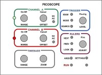
A control panel for your Picoscope, to make it resemble a traditional stand-alone 'scope, with knobs and buttons to control the main functions.
I'm an "old school" engineer, and want to make my Picoscope resemble a traditional stand-alone 'scope, with knobs and buttons to control the main functions (vertical range, timebase, trigger level, etc, etc.) rather than using the mouse. So I have built a simple control panel with rotary encoders and push buttons to do this. It works by emulating a keyboard, i.e. each rotary encoder or button sends one or several characters, and the picoscope keyboard shortcuts are set up to interpret these as required. Picoscope keyboard shortcuts allow many of the 'scope functions to be assigned to keys.
My Picoscope is model 2205 MSO, but the control panel can be used with any model.
The control panel is based on a Microchip PIC18F25K50 in 28 pin SOIC package. This has a built-in USB interface which greatly simplifies the design. The C code to control the USB interface comes from Microchip's MLA library of applications, specifically the app for HID Keyboard using PIC18F25K50. This avoids the need to write a lot of rather complicated code, and requires only minor edits for this project. The rest of the code which I have written is of course also in C.
The schematic and PCB are designed with DesignSpark PCB version 8.0.
The schematic is quite simple, in essence just 8 rotary encoders and 12 button switches plus PIC chip and USB connector. The rotary encoders also have a push switch, making 20 switches in total. Simple resistor networks are used so that the 20 switches require only two pins on the uP. On chip ADCs measure pin voltage and thus determine which button is pressed. This scheme does not work for the encoder rotation inputs, so they require two pins for each encoder.
The PCB is double-sided, home built, with quite relaxed track widths and spacings. The rotary encoders, USB connector, programming socket and two LEDs are through-hole; all the rest of components are surface mount. I prefer SM where possible because I think it give much more flexibility to board layout. In fact, the button sitches are actually through-hole, but I have bent the leads and snipped off most of the length to make them SM. They have a custom SM footprint.
I have not included a picture of my completed version 1 board as it has many hand-wired modifications, as is inevitable with the first build. The biggest mistake was to think that I could save more pins by having one common pin for all the rotary encoder "B" terminals; this does not work. There are further comments on rotary encoders in the schematic. The attached documents are for version 2 which has not yet been built, so correctness cannot be guaranteed at this time.
Also, I have not included any info on case construction at present. My version 1 prototype is just mounted on a aluminium sheet which is slightly larger than the PCB. However, I have included a Word doc with picture of printed logos for the front panel.
Power is derived from the USB port. Current drain is approx 13mA.
Note that if you place the cursor in an active document window, eg a text editor, and operate the controls then the keyboard characters will be printed. This can be useful for debug.
The keyboard mapping and 'scope functions are completely flexible; you may wish to change the panel layout and/or code to suit your own preferences. My keyboard mapping is defined by the attached KeyMapping.xlsx spreadsheet and the preferences file from Picoscope, which I have saved here as a text file preferences_xml.txt. But to repeat, you can ignore these and use your own key choices, just as long as Picocsope allows a keyboard shortcut to the function you require.
The code does not use interrupts; it relies on capturing the status of switches and rotary encoders "on the fly". This works perfectly well, but I expect there is room for improvements to my code.
MLA files were originally copied from:
"C:\Microchip\mla\v2016_04_27\apps\usb\device\hid_keyboard\firmware\picdem_fs_usb_k50.x"
Also, for USB keyboard, see Application Note AN1212
Discussie (1 opmerking(en))