
4 Channel Remote control by 433 MHz radios
Some of my young friends claimed that the 4 channel servo with XBEE though very sophisticated & robust but a bit costlier therefore, they asked for a cheaper solution. Well I tried the same with 433 MHz radios and here comes the result – it's little slow but works precisely.
Some of my young friends claimed that the 4 channel servo with XBEE though very sophisticated & robust but a bit costlier therefore, they asked for a cheaper solution. Well I tried the same with 433 MHz radios and here comes the result – it's little slow but works precisely.
433 MHz radio: These are very cheap radios operate at 433 MHz frequency. The operating voltage is from 5 volt upto 12 volt. Above 12 volt it will fry for sure. These radios come in separate transmitter and receiver or a single transceiver model. The cost of a single Tx & Rx pair comes for as cheap as Rs:300 in Mumbai market.
Our Project: We are aiming for developing a 4 channel wireless controller with one Arduino at each end .The Tx arduino will run 4 potentiometer which will deliver 4 analog values through the 433 MHz radio which will be deciphered by the Receiver radio followed by interpretation by the Arduino which in turn will do the remote jobs like running a brushless motor, controlling the Rudder , the Aileron and the elevator of a small air craft.
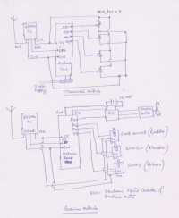
Schematic:
Tx module:
I've used one Arduino Uno board for this purpose. The tiny Tx not even bigger than an 1 Rupee coin is connected with the on board 5volt of Arduino Uno. The ground pin is connected with the Arduino ground and the data pin of it is connected to D12 (Digital pin 12) of Uno board. Four 10K POT each connected to Analog pin no: 0,1,2,3 respectively. After transferring the sketches the Uno board will be powered by 9volt external power jack through the socket (Because by that time it has to be free and you wont need the laptop connected to it) . In order to increase the transmission range the VCC of the 433 Mhz Tx. may be connected with 9volt + of the socket.
Rx module:
Here I've used one Arduino nano board. The connections are fairly simple and straight forward. The data wire of the Rx is connected with the D11 (digital pin 11 ) of Nano board. The VCC of the Rx goes to 5V pin of nano and all the ground connections are connected with the ground pin of Nano.
Four digital wires- D8,D9,D10,D12 are connected with the signal pin of ESC (Electronic Speed Controler), Servo1, Servo2 and Servo3 respectively - Servo1 for the Radder , Servo2 for the elevator, Servo3 for the Aileron. The power cables of the servos are connected with the 5V on board Nano and the ground wires are all connected with the ground pin of Nano.
Since the ESC requires high power of 12 volt the Nano board is back charged from this power. The 12V + wire is connected to the Vin pin of Nano while the ground is connected with the ground pin of Nano. As long as the Vin is not above 12Volt the Nano board will work safely without getting fried.
[Figure-1]
Connections:
Tx Sketch : 433-mhz-send-data.ino
#include < virtualwire.h >
const int numberOfAnalogPins = 4; // how many analog pins to read
int data[numberOfAnalogPins]; // the data buffer
const int dataBytes = numberOfAnalogPins * sizeof(int);
void setup() {
// Initialize the IO and ISR
vw_set_ptt_inverted(true); // Required for DR3100
vw_setup(2000); // Bits per sec
}
void loop() {
int values = 0;
for(int i=0; i <= numberOfAnalogPins; i++) {
data[i] = analogRead(i); // store the values into the data buffer
}
send((byte*)data, dataBytes);
delay(500); //send every second
}
void send (byte *data, int nbrOfBytes) {
vw_send(data, nbrOfBytes);
vw_wait_tx(); // Wait until the whole message is gone
}
RX Sketch: 433-mhz-receive-data.ino
#include < softwareservo.h >
#include < softwareserial.h >
#include < virtualwire.h >
SoftwareServo myservo1;
SoftwareServo myservo2;
SoftwareServo myservo3;
SoftwareServo myservo4;
const int numberOfAnalogPins = 4; // how many analog integer values to receive
int data[numberOfAnalogPins]; // the data buffer
int value[numberOfAnalogPins];
// the number of bytes in the data buffer
const int dataBytes = numberOfAnalogPins * sizeof(int);
byte msgLength = dataBytes;
int dl=20;
void setup() {
myservo1.attach(9); //Propeller
myservo2.attach(10); //Radar
myservo3.attach(8); // Aeleron
myservo4.attach(12); // Elevator
Serial.begin(9600);
Serial.println("Ready");
// Initialize the IO and ISR
vw_set_ptt_inverted(true); // Required for DR3100
vw_setup(2000); // Bits per sec
vw_set_rx_pin(11);
vw_rx_start(); // Start the receiver
}
void loop(){
if (vw_get_message((byte*)data, &msgLength)) { // Non-blocking
Serial.println("Got: ");
if(msgLength == dataBytes){
for (int i = 0; i < numberOfAnalogPins; i++) {
Serial.print("pin ");
Serial.print(i);
Serial.print("=");
Serial.println(data[i]);
value[i]=map(data[i],0,1023,0,179); // Write into the servo
}
SoftwareServo::refresh(); //refresh the servo
myservo1.write(value[0]);
delay(dl);
SoftwareServo::refresh(); //refresh the servo
myservo2.write(value[1]);
myservo3.write(value[2]);
myservo4.write(value[3]);
delay(dl);
SoftwareServo::refresh(); //refresh the servo
}
else {
Serial.print("unexpected msg length of ");
Serial.println(msgLength);
}
Serial.println();
}
}
433 MHz radio: These are very cheap radios operate at 433 MHz frequency. The operating voltage is from 5 volt upto 12 volt. Above 12 volt it will fry for sure. These radios come in separate transmitter and receiver or a single transceiver model. The cost of a single Tx & Rx pair comes for as cheap as Rs:300 in Mumbai market.
Our Project: We are aiming for developing a 4 channel wireless controller with one Arduino at each end .The Tx arduino will run 4 potentiometer which will deliver 4 analog values through the 433 MHz radio which will be deciphered by the Receiver radio followed by interpretation by the Arduino which in turn will do the remote jobs like running a brushless motor, controlling the Rudder , the Aileron and the elevator of a small air craft.
Schematic:
Tx module:
I've used one Arduino Uno board for this purpose. The tiny Tx not even bigger than an 1 Rupee coin is connected with the on board 5volt of Arduino Uno. The ground pin is connected with the Arduino ground and the data pin of it is connected to D12 (Digital pin 12) of Uno board. Four 10K POT each connected to Analog pin no: 0,1,2,3 respectively. After transferring the sketches the Uno board will be powered by 9volt external power jack through the socket (Because by that time it has to be free and you wont need the laptop connected to it) . In order to increase the transmission range the VCC of the 433 Mhz Tx. may be connected with 9volt + of the socket.
Rx module:
Here I've used one Arduino nano board. The connections are fairly simple and straight forward. The data wire of the Rx is connected with the D11 (digital pin 11 ) of Nano board. The VCC of the Rx goes to 5V pin of nano and all the ground connections are connected with the ground pin of Nano.
Four digital wires- D8,D9,D10,D12 are connected with the signal pin of ESC (Electronic Speed Controler), Servo1, Servo2 and Servo3 respectively - Servo1 for the Radder , Servo2 for the elevator, Servo3 for the Aileron. The power cables of the servos are connected with the 5V on board Nano and the ground wires are all connected with the ground pin of Nano.
Since the ESC requires high power of 12 volt the Nano board is back charged from this power. The 12V + wire is connected to the Vin pin of Nano while the ground is connected with the ground pin of Nano. As long as the Vin is not above 12Volt the Nano board will work safely without getting fried.
[Figure-1]
Connections:
Tx Sketch : 433-mhz-send-data.ino
#include < virtualwire.h >
const int numberOfAnalogPins = 4; // how many analog pins to read
int data[numberOfAnalogPins]; // the data buffer
const int dataBytes = numberOfAnalogPins * sizeof(int);
void setup() {
// Initialize the IO and ISR
vw_set_ptt_inverted(true); // Required for DR3100
vw_setup(2000); // Bits per sec
}
void loop() {
int values = 0;
for(int i=0; i <= numberOfAnalogPins; i++) {
data[i] = analogRead(i); // store the values into the data buffer
}
send((byte*)data, dataBytes);
delay(500); //send every second
}
void send (byte *data, int nbrOfBytes) {
vw_send(data, nbrOfBytes);
vw_wait_tx(); // Wait until the whole message is gone
}
RX Sketch: 433-mhz-receive-data.ino
#include < softwareservo.h >
#include < softwareserial.h >
#include < virtualwire.h >
SoftwareServo myservo1;
SoftwareServo myservo2;
SoftwareServo myservo3;
SoftwareServo myservo4;
const int numberOfAnalogPins = 4; // how many analog integer values to receive
int data[numberOfAnalogPins]; // the data buffer
int value[numberOfAnalogPins];
// the number of bytes in the data buffer
const int dataBytes = numberOfAnalogPins * sizeof(int);
byte msgLength = dataBytes;
int dl=20;
void setup() {
myservo1.attach(9); //Propeller
myservo2.attach(10); //Radar
myservo3.attach(8); // Aeleron
myservo4.attach(12); // Elevator
Serial.begin(9600);
Serial.println("Ready");
// Initialize the IO and ISR
vw_set_ptt_inverted(true); // Required for DR3100
vw_setup(2000); // Bits per sec
vw_set_rx_pin(11);
vw_rx_start(); // Start the receiver
}
void loop(){
if (vw_get_message((byte*)data, &msgLength)) { // Non-blocking
Serial.println("Got: ");
if(msgLength == dataBytes){
for (int i = 0; i < numberOfAnalogPins; i++) {
Serial.print("pin ");
Serial.print(i);
Serial.print("=");
Serial.println(data[i]);
value[i]=map(data[i],0,1023,0,179); // Write into the servo
}
SoftwareServo::refresh(); //refresh the servo
myservo1.write(value[0]);
delay(dl);
SoftwareServo::refresh(); //refresh the servo
myservo2.write(value[1]);
myservo3.write(value[2]);
myservo4.write(value[3]);
delay(dl);
SoftwareServo::refresh(); //refresh the servo
}
else {
Serial.print("unexpected msg length of ");
Serial.println(msgLength);
}
Serial.println();
}
}
Discussie (5 opmerking(en))