
Energy saving solid-state feet warmer
In these times of extreme high energy prices (nov 2022), people are forced to think about saving energy in all kinds of ways. This project is an attempt to get a warm feeling with a relative low amount of energy.
Introduction
With the extreme high energy prices at the time of writing (nov. 2022) I thought it would be interesting to have a way to keep the feet or hands warm, while keeping the gas central heating at a low temperature to save costs.
Most electrical heaters that use convection or radiation to transfer heat need quite a bit of power (1000 to over 2000W) to heat up the air or objects at a distance in a relative short time. When you want to have a more direct heat transfer that requires less power, heat conduction with direct contact to your body is the way to go. On the other hand, the best way to resist the cold is to keep your feet warm, because that gives an overall comfortable feeling.
So what if we combine heat transfer by conduction and use that to warm the feet? That would require a relative low power and still gives us a comfortable feeling.
For heat transfer by conduction we need a metal plate that has a good thermal conductivity so the heat that is produced spreads easily over the entire area of the plate . Copper, silver or gold would be ideal, but then we wouldn't have to worry about energy costs. Aluminum is a good alternative though.
How thick should the plate be. If we'd use a plate of lets exaggerate, 1 cm thick, it would take quite some time to warm up the whole plate, but once warmed up, it would be easier to keep the plate up to temperature due to the high heat capacitance of a thick plate. But we don't want to wait for an hour before our plate is heated up. An aluminum plate with a thickness of 2 mm will be fine, so heating the volume of material up doesn't take too long (minutes) .
To warm up our feet we will need the plate to warm up to about 40 to 45 degrees wearing socks. We need to overcome the thermal resistance of the socks.
Why not bare feet? In fact to increase safety as we will see later.
Can we calculate or predict how much time it takes to heat up an aluminum plate when using an certain electrical power ?
We can use the following formulate to get a rough idea:
Time needed to heat up a volume of aluminum (seconds) =Energy capacity of aluminum (J/(gram * degrees Celsius)) * volume (cm3) * density(gram/cm3) * delta temperature (degrees Celsius) / input power (Joule/second)
When we fill in the values, we get:
Time = (0.902 * (35 * 25 * 0.2) * 2.7 * 28) / 60 = 198 seconds = 3.3 minutes.
So by inputting 60W of power, it lasts 3.3 minutes to increase the temperature of the aluminum plate by 28 degrees Celsius.
This means that it would take 6.6 minutes when using 30W or 13.2 minutes with 15W to increase the temperature by 28 degrees Celsius.
Of course this is theory and we know that the difference between practice and theory is always larger in practice.
There will be some additional losses due to inefficient power transfer, thermal resistance between the heating device and the aluminum plate, density difference in the aluminum, do we know exactly what type of aluminum alloy we are using, etc...But we can say that when we can adjust the input power between ca. 20W and ca. 70W, we will have a comfortable temperature to warm the feet in low ambient temperatures without waiting very long for the plate to be heated up. I used the feet warmer at 14 degrees Celsius ambient temperature with an input power of about ca. 30W to get my feet (in thick socks) warmed up to ca. 35 degrees.
We didn't talk yet about how to heat up the plate. This is explained below.
Schematic
Why call it a solid state feet warmer ?
For the heat production, we use 8x bipolar power transistors. These are TIP41C NPN power transistors. These can handle a max. total power dissipation of 65W when we keep their case at 25 degrees Celsius and a collector current of max. 6A. I've chosen this type because i had enough of them lying around and i wanted to use a device with a TO-220 casing because that is easy to screw down on an aluminum plate and is big enough to transfer an amount of heat into the plate. A device in a TO-247 case can also be used, but that is even more overkill since these are used for devices with close to 100W of power.
Since we are using 8 power transistors, each transistor only needs to handle max. 10W.
Why do we use 8x power transistors ?
I wanted to prevent having hot-spots on the plate and have the heat nicely spread out over the total area of the plate. Maybe 6 power transistors would also be fine, but i had plenty of TIP41C power transistors lying around, so i decided to play safe. By distributing the 8x power transistors equally over the area of the plate, you certainly don't feel hot spots on the plate at the locations where the transistors are mounted to the plate.
In the schematic Q1, Q2, Q5, Q6, Q8, Q9, Q11, Q12 are the heat producing power transistors i'm talking about.
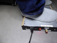
The aluminum plate i used is 2mm thick and has a size of 35cm x 25cm. Be aware that when you take an aluminum plate that is twice as thick, you will need to wait twice as long before the plate is heated up or you have to increase the input power with a factor 2 to speed up the process.
Now we come to the question of how to implement the temperature control and how to measure the temperature.
I didn't want to use an on-off temperature control as is commonly used with a thermostat so the temperature oscillates up to the set temperature. I decided to use an analog proportional temperature control because that gives a nice steady temperature without any on-off behavior.
To measure the temperature i used the same type of power transistor as is used for the heating, because again i had enough of them lying around , but also because they are easy to mount and give a good thermal contact with the aluminum plate. When using an NTC thermistor you still need to figure out how to make a good thermal contact with the plate. So a power transistor is ideal in that sense.
The temperature sensor is transistor Q4 in the schematic. The negative temperature coefficient of the base-emitter junction of Q4 is used to control the temperature of the plate. The base-emitter voltage of Q4 will drop in a rather linear way with rising temperature in the temperature range that we need.
It is not uncommon to use either diodes or base-emitter junctions of bipolar transistors to measure temperature.
The temperature related base emitter voltage of Q4 is amplified ca. 3x by the OPAMP U1A (LM324) which is configured as a non-inverting amplifier. The output voltage of this OPAMP is used to control the voltage over potmeter P1 that is used to set the power that goes into the heater transistors. The voltage at the potmeter is buffered by OPAMP U1B which is configured as a voltage follower with a current booster, formed by Q3 and Q7. The current booster provides the current for the bases of the 8 power transistors.
When P1 is set to a certain value, the power transistors will start heating up the aluminum plate with a power close to the maximum power.
While the plate is heating up, the voltage over the base-emitter junction of Q4 will start dropping along with the rising temperature. When this voltage drops, this means that the voltage at the junction between R7 and P1 decreases. This means that U1B will provide less and less current to the bases of the 8 power transistors while the plate is heating up. So the temperature rise will "slow" down to the point where a balance is reached between the temperature generated by the power transistors and the temperature sensed by the temperature sensor. At which temperature this balance will be reached is determined by the position of P1 and the ambient temperature that the plate has to conquer.
The maximum current is limited by a current limiter formed with the circuit around U1C. The voltage across the emitter resistors of Q8 (2x 0R47 parallel) is used to measure the current that is flowing through the transistor. We can assume that all 8x transistors draw about the same current, so it is enough to measure the current through one of them to know the total current drawn by all 8x power transistors together.
The current limit is set with P2 so the total current drawn by all 8x power transistors together is maximum 5A. So the current through one of the power transistors should be maximum ca. 5A /8 = 0.63A. A current of 0.63A through the 2x parallel 0R47 emitter resistors (=0R235) results in a voltage of
0.63A * 0R235 = ca. 150mV. U1C compares this voltage to a the voltage set by P2. The voltage set by P2 is derived from a stable voltage reference U2 (TL431).
U2 is configured to output a 2.5V reference voltage, independent of temperature or input voltage, so our current limit setting is not affected by input voltage or temperature fluctuations. The PCB is mounted close to the plate, so we need to make sure that the temperature does not affect the setting of the current limiter. When the voltage over the emitter resistors of Q8 becomes higher than the voltage set by P2, the output of U1C will swing to the positive voltage rail. This will cause Q10 to conduct and will pinch down the voltage set by P1 to nearly 0 volts. This means that the power going to the power transistors gets cut off when the total current drawn by the 8x power transistors would exceed 5A. This way the current limiter protects the 8x power transistors and makes sure that the maximum power can never be exceeded. C1 is there to keep the current limiter from causing instability (high frequency oscillation) that would affect the temperature control loop.
F.e. when the plate is cold, the temperature sensor voltage will be maximum (low temperature), so the power transistors get maximum base voltage/current and would draw a large current when we wouldn't use a current limiter. Once the plate is warmed up, the voltage over the temperature sensor will progressive decrease, thereby decreasing the current going through the 8x power transistors.
So only at the beginning, when the plate is cold, we need to limit the current so the power transistors always operate in their safe operation area and so the maximum power of the power adapter, that is powering the feet warmer, is not exceeded. It is good to have a current limit anyways to protect the electronics and power adapter just in case things go wrong.
The 12V DC input voltage is supplied by a switching power adapter that can deliver a maximum of 72 Watts of power at 12V, which means it can deliver a maximum current of 6A.
Safety warning:
When the collectors of the power transistors are all electrically connected to the aluminum plate, the plate will carry a the input voltage of 12V DC. I didn't use a medical rated power supply with a guaranteed high voltage isolation, so for safety, use a silicon thermal pad (Sil-pad), mica and isolation kits for each of the 8 power transistors that are mounted to the plate, so their collectors are electrically isolated from the plate.
The collector of the transistor that is used as a temperature sensor should also be electrically isolated from the aluminum plate.
With the extreme high energy prices at the time of writing (nov. 2022) I thought it would be interesting to have a way to keep the feet or hands warm, while keeping the gas central heating at a low temperature to save costs.
Most electrical heaters that use convection or radiation to transfer heat need quite a bit of power (1000 to over 2000W) to heat up the air or objects at a distance in a relative short time. When you want to have a more direct heat transfer that requires less power, heat conduction with direct contact to your body is the way to go. On the other hand, the best way to resist the cold is to keep your feet warm, because that gives an overall comfortable feeling.
So what if we combine heat transfer by conduction and use that to warm the feet? That would require a relative low power and still gives us a comfortable feeling.
For heat transfer by conduction we need a metal plate that has a good thermal conductivity so the heat that is produced spreads easily over the entire area of the plate . Copper, silver or gold would be ideal, but then we wouldn't have to worry about energy costs. Aluminum is a good alternative though.
How thick should the plate be. If we'd use a plate of lets exaggerate, 1 cm thick, it would take quite some time to warm up the whole plate, but once warmed up, it would be easier to keep the plate up to temperature due to the high heat capacitance of a thick plate. But we don't want to wait for an hour before our plate is heated up. An aluminum plate with a thickness of 2 mm will be fine, so heating the volume of material up doesn't take too long (minutes) .
To warm up our feet we will need the plate to warm up to about 40 to 45 degrees wearing socks. We need to overcome the thermal resistance of the socks.
Why not bare feet? In fact to increase safety as we will see later.
Can we calculate or predict how much time it takes to heat up an aluminum plate when using an certain electrical power ?
We can use the following formulate to get a rough idea:
Time needed to heat up a volume of aluminum (seconds) =Energy capacity of aluminum (J/(gram * degrees Celsius)) * volume (cm3) * density(gram/cm3) * delta temperature (degrees Celsius) / input power (Joule/second)
- Heat capacity of aluminum = 0.902 J/g degrees Celsius
- Volume of the aluminum plate = 35cm x 25cm x 0.2cm = 175cm3
- density of aluminum = 2.7g/cm3
- Temperature change that we need = 45 degrees - 17 degrees = 28 degrees Celsius
- Input power that we want to apply = 60W = J/s
When we fill in the values, we get:
Time = (0.902 * (35 * 25 * 0.2) * 2.7 * 28) / 60 = 198 seconds = 3.3 minutes.
So by inputting 60W of power, it lasts 3.3 minutes to increase the temperature of the aluminum plate by 28 degrees Celsius.
This means that it would take 6.6 minutes when using 30W or 13.2 minutes with 15W to increase the temperature by 28 degrees Celsius.
Of course this is theory and we know that the difference between practice and theory is always larger in practice.
There will be some additional losses due to inefficient power transfer, thermal resistance between the heating device and the aluminum plate, density difference in the aluminum, do we know exactly what type of aluminum alloy we are using, etc...But we can say that when we can adjust the input power between ca. 20W and ca. 70W, we will have a comfortable temperature to warm the feet in low ambient temperatures without waiting very long for the plate to be heated up. I used the feet warmer at 14 degrees Celsius ambient temperature with an input power of about ca. 30W to get my feet (in thick socks) warmed up to ca. 35 degrees.
We didn't talk yet about how to heat up the plate. This is explained below.
Schematic
Why call it a solid state feet warmer ?
For the heat production, we use 8x bipolar power transistors. These are TIP41C NPN power transistors. These can handle a max. total power dissipation of 65W when we keep their case at 25 degrees Celsius and a collector current of max. 6A. I've chosen this type because i had enough of them lying around and i wanted to use a device with a TO-220 casing because that is easy to screw down on an aluminum plate and is big enough to transfer an amount of heat into the plate. A device in a TO-247 case can also be used, but that is even more overkill since these are used for devices with close to 100W of power.
Since we are using 8 power transistors, each transistor only needs to handle max. 10W.
Why do we use 8x power transistors ?
I wanted to prevent having hot-spots on the plate and have the heat nicely spread out over the total area of the plate. Maybe 6 power transistors would also be fine, but i had plenty of TIP41C power transistors lying around, so i decided to play safe. By distributing the 8x power transistors equally over the area of the plate, you certainly don't feel hot spots on the plate at the locations where the transistors are mounted to the plate.
In the schematic Q1, Q2, Q5, Q6, Q8, Q9, Q11, Q12 are the heat producing power transistors i'm talking about.
The aluminum plate i used is 2mm thick and has a size of 35cm x 25cm. Be aware that when you take an aluminum plate that is twice as thick, you will need to wait twice as long before the plate is heated up or you have to increase the input power with a factor 2 to speed up the process.
Now we come to the question of how to implement the temperature control and how to measure the temperature.
I didn't want to use an on-off temperature control as is commonly used with a thermostat so the temperature oscillates up to the set temperature. I decided to use an analog proportional temperature control because that gives a nice steady temperature without any on-off behavior.
To measure the temperature i used the same type of power transistor as is used for the heating, because again i had enough of them lying around , but also because they are easy to mount and give a good thermal contact with the aluminum plate. When using an NTC thermistor you still need to figure out how to make a good thermal contact with the plate. So a power transistor is ideal in that sense.
The temperature sensor is transistor Q4 in the schematic. The negative temperature coefficient of the base-emitter junction of Q4 is used to control the temperature of the plate. The base-emitter voltage of Q4 will drop in a rather linear way with rising temperature in the temperature range that we need.
It is not uncommon to use either diodes or base-emitter junctions of bipolar transistors to measure temperature.
The temperature related base emitter voltage of Q4 is amplified ca. 3x by the OPAMP U1A (LM324) which is configured as a non-inverting amplifier. The output voltage of this OPAMP is used to control the voltage over potmeter P1 that is used to set the power that goes into the heater transistors. The voltage at the potmeter is buffered by OPAMP U1B which is configured as a voltage follower with a current booster, formed by Q3 and Q7. The current booster provides the current for the bases of the 8 power transistors.
When P1 is set to a certain value, the power transistors will start heating up the aluminum plate with a power close to the maximum power.
While the plate is heating up, the voltage over the base-emitter junction of Q4 will start dropping along with the rising temperature. When this voltage drops, this means that the voltage at the junction between R7 and P1 decreases. This means that U1B will provide less and less current to the bases of the 8 power transistors while the plate is heating up. So the temperature rise will "slow" down to the point where a balance is reached between the temperature generated by the power transistors and the temperature sensed by the temperature sensor. At which temperature this balance will be reached is determined by the position of P1 and the ambient temperature that the plate has to conquer.
The maximum current is limited by a current limiter formed with the circuit around U1C. The voltage across the emitter resistors of Q8 (2x 0R47 parallel) is used to measure the current that is flowing through the transistor. We can assume that all 8x transistors draw about the same current, so it is enough to measure the current through one of them to know the total current drawn by all 8x power transistors together.
The current limit is set with P2 so the total current drawn by all 8x power transistors together is maximum 5A. So the current through one of the power transistors should be maximum ca. 5A /8 = 0.63A. A current of 0.63A through the 2x parallel 0R47 emitter resistors (=0R235) results in a voltage of
0.63A * 0R235 = ca. 150mV. U1C compares this voltage to a the voltage set by P2. The voltage set by P2 is derived from a stable voltage reference U2 (TL431).
U2 is configured to output a 2.5V reference voltage, independent of temperature or input voltage, so our current limit setting is not affected by input voltage or temperature fluctuations. The PCB is mounted close to the plate, so we need to make sure that the temperature does not affect the setting of the current limiter. When the voltage over the emitter resistors of Q8 becomes higher than the voltage set by P2, the output of U1C will swing to the positive voltage rail. This will cause Q10 to conduct and will pinch down the voltage set by P1 to nearly 0 volts. This means that the power going to the power transistors gets cut off when the total current drawn by the 8x power transistors would exceed 5A. This way the current limiter protects the 8x power transistors and makes sure that the maximum power can never be exceeded. C1 is there to keep the current limiter from causing instability (high frequency oscillation) that would affect the temperature control loop.
F.e. when the plate is cold, the temperature sensor voltage will be maximum (low temperature), so the power transistors get maximum base voltage/current and would draw a large current when we wouldn't use a current limiter. Once the plate is warmed up, the voltage over the temperature sensor will progressive decrease, thereby decreasing the current going through the 8x power transistors.
So only at the beginning, when the plate is cold, we need to limit the current so the power transistors always operate in their safe operation area and so the maximum power of the power adapter, that is powering the feet warmer, is not exceeded. It is good to have a current limit anyways to protect the electronics and power adapter just in case things go wrong.
The 12V DC input voltage is supplied by a switching power adapter that can deliver a maximum of 72 Watts of power at 12V, which means it can deliver a maximum current of 6A.
Safety warning:
When the collectors of the power transistors are all electrically connected to the aluminum plate, the plate will carry a the input voltage of 12V DC. I didn't use a medical rated power supply with a guaranteed high voltage isolation, so for safety, use a silicon thermal pad (Sil-pad), mica and isolation kits for each of the 8 power transistors that are mounted to the plate, so their collectors are electrically isolated from the plate.
The collector of the transistor that is used as a temperature sensor should also be electrically isolated from the aluminum plate.
Discussie (2 opmerking(en))