
FM Radio Receiver with RDS for Raspberry Pi [160520]
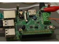
FM Radio Receiver with RDS using a Raspberry Pi. 2x2 W (1%, 4 Ω) Class-D power amplifier is included. AM reception is also supported by the hardware.
Designed by:
HTBLA STEYR
Elektronik und Technische Informatik
Fabian Bugelmüller, Christoph Fornezzi,
AV Dipl.-Ing. Franz Parzer
An app is available with IR remote control working:
https://www.elektormagazine.com/labs/piradio-for-fm-radio-receiver-with-rds-for-raspberry-pi-160520-1
Abstract
This thesis deals with the design of a hardware for the Raspberry Pi to receive FM broadcasts with RDS and to play back audio through the same hardware. The transmission of audio data should be digital. The hardware is developed according to HAT specifications. Furthermore, it should be possible to control the radio by means of an IR transmitter. The IC Si4731 from Silicon Laboratories is used as the radio receiver and the SSM2518 was chosen as the power amplifier. I2C is used for transmitting the control commands, and the I2S interface for audio data. The Raspberry Pi serves as a master for all operations. As a secondary goal, the project should be prepared in such a way, that the radio can be produced in the workshop and to acquaint students with the SMD assembly.
Preface
Linux
Since the hardware was designed for the Raspberry Pi, and the most widespread operating system for the RPi is Linux based it was decided to develop the drivers for Linux. Linux is open source and thus the code for all functions is accessible and simplifies the development for this operating system. Two different Linux distributions were chosen: Raspbian and Volumio.
Raspbian
Raspbian is based on Debian and optimized for the Raspberry Pi hardware. The main focus of these optimizations is the adjustment of the operating system to the ARM processor of the RPi. Raspbian is packed with a lot of preinstalled programs and a desktop interface. More information: https://www.raspbian.org. In Raspbian the software Kradio4 can be used to control the receiver and must be installed additionally. To output the audio stream via the onboard power amplifier a playback program like aplay is used. It’s already installed in Raspbian by default.
Volumio
Volumio is also based on Debian but specializes on playback of Audio only. Volumio can play many different audio formats like mp3, wav and flac to name but a few. Compared to Raspbian Volumio is more energy efficient because functions of no use for audio are disabled. There is no desktop but instead a WebUI is used making control of playback possible by using for instance a PC or a mobile phone. More information here: https://volumio.org.
ALSA sound system
The Advanced Linux Sound Architecture (ALSA) provides audio and MIDI functionality to the Linux operating system. It supports many devices like sound cards and audio interfaces. Purpose of the ALSA system is an easy configuration of audio devices and an easier handling of multiple sound cards. To achieve this an alsa-lib is provided to program custom drivers. The idea is a detailed description of a sound card. It starts with card, followed by devices and subdevices. The interface describes the ALSA protocol. Interfaces available are hw, plughw and default. The hw protocol describes the direct access to a kernel-device without support for further software processing. Typical for the data stream is the PCM format. Parameters for this format are for instance sampling rate (typ. 44.1 kHz or 48 kHz), the number of bits per sample (typ. 16 bit) and the number of channels (often 2). Listing 1 shows the ALSA playback hardware devices, listed in Linux with the command aplay -l. Listing 2 shows the playback devices and their available interfaces, listed in the command aplay –L.
Listing 1 (output of aplay -l):
**** List of PLAYBACK Hardware Devices ****
card 0: rpiReceiver [rpiReceiver], device 0: bcm2835-i2s-ssm2518-hifi ssm2518-hifi-0 []
Subdevices: 1/1
Subdevice #0: subdevice #0
Listing 2 (output of aplay -L):
null
Discard all samples (playback) or generate zero samples (capture)
pulse
PulseAudio Sound Server
default
sysdefault:CARD=rpiReceiver
rpiReceiver,
Default Audio Device
dmix:CARD=rpiReceiver,DEV=0
rpiReceiver,
Direct sample mixing device
dsnoop:CARD=rpiReceiver,DEV=0
rpiReceiver,
Direct sample snooping device
hw:CARD=rpiReceiver,DEV=0
rpiReceiver,
Direct hardware device without any conversions
plughw:CARD=rpiReceiver,DEV=0
rpiReceiver,
Hardware device with all software conversions
Device Tree
The Device Tree describes the existing hardware in a system. It’s a tree structure as the name already states with nodes representing the devices. The description is entered in an Overlay file. That Overlay file is then loaded during boot and entered in the Device Tree. The Device Tree Source is written as a readable DTS file. A compiler (the program dtc) generates a binary DTB file (Device Tree Blob) from the Source File for the Device Tree.
Excerpt rpi-receiver-overlay.dts dated 23.02.2017 (tabs removed):
fragment@2 {
target = <&i2c1>;
__overlay__ {
#address-cells = <1>;
#size-cells = <0>;
status = "okay"; /* device is enabled */
ssm2518: ssm2518@34 {
#sound-dai-cells = <0>;
compatible = "adi,ssm2518";
reg = <0x34>;
pinctrl-names = "default";
pinctrl-0 = <&ssm2518_pins>;
gpios = <&gpio 17 0>; /* for ssm2518*/
status = "okay"; /* device is enabled */
};
si4731: si4731@63 {
#sound-dai-cells = <0>;
compatible = "si,si4731";
reg = <0x63>;
pinctrl-names = "default";
pinctrl-0 = <&si473x_pins>;
gpios = <&gpio 23 1>; /* for si4731*/
interrupt-parent = <&gpio>;
interrupts = <22 2>; /* falling edge */
fm_seek_tune_rssi_treshold = /bits/ 16 <0x0014>;
fm_seek_tune_snr_threshold = /bits/ 16 <0x0003>;
fm_max_tune_error = /bits/ 16 <0x0014>;
am_seek_rssi_threshold = /bits/ 16 <0x0019>;
am_seek_snr_threshold = /bits/ 16 <0x0005>;
status = "okay"; /* device is enabled */
};
};
};
The Overlay file consists of different parts as can be seen in the listing. Fragment@2 shows a detail of this file. Property ‘target’ describes to which nodes in the Device-Tree, listed after __overlay__, should be attached. In the example here they should be attached to the nodes of the I2C bus with number 1.
ssm2518: ssm2518@34 designates a new node being created. ssm2518 is a label for referencing and ssm2518@34 is the name of the new node as well as its address in the Device-Tree. Those properties that can’t be recognized by a Program should be added here. Especially important is the property ‘compatible’ because it connects de hardware with the associated drivers. Consequently the property ‘.compatible’ must be defined in the driver. Passage from si473x-i2c.c:
#ifdef CONFIG_OF
static const struct of_device_id si473x_dt_ids[] = {
{ .compatible = "si,si4731", },
{ }
};
MODULE_DEVICE_TABLE(of, si473x_dt_ids);
#endif
Property ‘status’ indicates if the hardware is active (okay) or inactive (disabled). If for example a reference is found like it means the necessary information can be found in a different node with the same label.
Hardware
The following requirements were put to the board:
The receiver should be designed as a HAT for a Raspberry Pi. It should be able to receive FM broadcasting + RDS and passed on digitally via I2S to the RPi. The board should contain an audio amplifier that receives it audio data via I2S. Additionally the board should have an infra-red-receiver to control the receiver remotely.
HAT
HAT stands for Hardware Attached on Top and means an Add-on board designed as a HAT has to comply with HAT-specifications. The board will be attached to the 40 pins expansion connector of the RPi. 2 of the 40 pins (ID_SC and ID_SD) are solely used to connect an ID-EEPROM. In this EEPROM is information about the board, its functions, configuration of the GPIO pins and how the combination of RPi and HAT is powered (by way of micro-USB of the RPi or the HAT).
HAT specifications:
- It complies with the basic add-on conditions
- Valid data in the EEPROM (Vendor info, GPIO map and valid Device-Tree information)
- 40 pin socket
- Mechanical regulations: board must be 10 to 12 mm above the RPi, dimensions
- If powered by the HAT, it must be ensured 1.3 A is always available for the RPi
EEPROM
Since the hardware complies with the HAT specifications an EEPROM is needed. According to specifications R1 should be 1 kΩ but we use 3.9 kΩ. This way less different resistor values are needed for production of the board.
LIRC
(Linux Infrared Remote Control)
The receiver can be controlled remotely by infrared this way. The component receives the infrared signal and passes the signal on to GPIO26 of the RPi. The RPi will interpret the infrared signal and execute the assigned commands.
Si4731
It was decided to use the Si4731 D62 of Silicon Laboratories as the receiver chip. It can receive FM and AM. It can also decode RDS and pass on data via I2S. It is configured through I2C. Because of the I2C and I2S interface it can be connected to the RPi directly.
The package type chosen is QFN (Quad Flat No-Lead) because it’s smaller than the SSOP package. The QFN package is only 3 x 3 mm in size, has 20 connections on the bottom side and is therefore about a sixth of the SSOP package.
Originally the receiver could receive FM in two different ways. One was by way of a power cable for the HAT or a FM antenna. It was decided to remove the power cable option because of poor quality reception (K1, C9 and L3 were removed from the design).
For proper reception L2 forms the resonance of the antenna. Suppressor diode D1 takes care of the ESD protection and C10 removes any DC component from the signal.
For AM reception a 470 nF capacitor (C11) is connected in series with the input as is done in the datasheet. A ferrite loop antenna of 180…450 µH must be used. C5 and C6 are decoupling capacitors for the power supply. L1 filters the analog power supply so it’s stable. 100 Ω resistors R8…R10 are added for protection and noise suppression.
SSM2518
The SSM2518 of Analog Devices is used as playback device. This class-D amplifier has a digital serial audio interface supporting I2S mode and can be controlled via I2C. Output power per channel in a 4 Ω load is 2 W. The circuitry is according to the typical application in the datasheet. A standard 100 nF ceramic capacitor (C7) decouples the 3.3 V digital power supply (DVDD). And the 5 V amplifier power supply is decoupled by a standard 100nF ceramic capacitor (C8) and an aluminum polymer capacitor (C1) to take care of peak currents. The polymer capacitor used has a very low ESR of only 30 mΩ. According to the datasheet output filters are only necessary when the wires to the speakers are longer than 20 cm. If the wires shorter these filters wouldn’t have to be used. But implementing the filters assures there’s no interference. Without the filters interference is high enough to make RDS reception impossible. Resistors R5 and R6 are pull-ups needed for I2C.
CS2300
An oscillator was used in previous versions. The main clock (generated by the oscillator) wasn’t synchronous with the I2S clock and bits were lost. As a solution to this problem a frequency multiplier is used instead, the SSM2300-CP-CZZ from Cirrus logic. It also has a I2C control port to configure modes and formats. The main clock should be 256 times the I2S clock. The I2S clock generated by the RPi is now multiplied by 256 to generate the main clock. The circuitry is according to the datasheet. The optional 10 pF capacitor (C16) connected parallel to the PLL clock output CLK_OUT can be left unmounted. It was added in case the level of the harmonics in the signal are too high, but is not needed in this version.
Board
Close attention was payed to keep different component groups of the receiver separated and logically positioned. Since the infrared receiver and EEPROM have no part in the main purpose of the board these are clearly separated from the rest of the component groups. The receiver IC is in the top part of the PCB, the frequency multiplier is placed in the middle and the class-D amplifier is located in the lower right corner.
A header is added to enable the write protection of the EEPROM (labeled WP). This way a jumper must be fitted first before the contents of the EEPROM can be changed.
The output filters of the class-D amplifier were positioned in such way that the inductors are as close as possible to the IC and the capacitors as close as possible to the terminals blocks of the speakers. Decoupling capacitor are also placed as close as possible to the IC.
The power supply peripherals, FM antenna input, AM antenna input, and component that are part of the digital outputs of the receiver IC are clearly separated.
Software
For the hardware to work under Linux special drivers must be written for the ICs used. It was decided to develop a sound card driver which combines all necessary components as a single device. But separate drivers are still necessary for the different components. To simplify the development of the drivers already existing driver sources were modified so they will work with the components used.
Drivers for the class-D amplifier already exist in the kernel that can be used. For the radio receiver the driver of the SI476x family was modified. Here most changes had to be made since two different families of components are concerned. Also for the frequency multiplier a driver for a different component had to be modified. For the sound card itself simple-card drivers were modified.
Basics of driver development
Because kernel modules have to be developed the file module.h must be included. With it license and module information can be assigned to the driver. There are three important functions here:
MODULE_AUTHOR("rpiReceiver ");
MODULE_DESCRIPTION("CS2300 driver");
MODULE_LICENSE("GPL");
The function MODULE_AUTHOR sets the name of the person who wrote the driver. MODULE_DESCRIPTION is a short description of the driver. MODULE_LICENSE sets the license used by the driver.
It should be noted devices are programmed and have to work together with the Device Tree. That’s why it’s important to include the file device.h (or the equivalent of a subsystem).
Since the components use I2C to communicate, I2C functions being included with i2c.h file are important.
static struct i2c_driver cs2300_driver = {
.driver = {
.name = "cs2300-cp",
.of_match_table = clk_cs2300_of_match,
},
.probe = cs2300_probe,
.remove = cs2300_remove,
.id_table = cs2300_id,
};
The i2c_driver structure represents the driver. It contains information about the driver like the name and which functions can be called, to get information like the compatible string that’s responsible for the assignment of the driver and the overlay.
The function called by .probe contains code to check whether it’s the right component, configures the component and finally registers the component in the system. The function called by .remove is responsible for the removal of the component from the system. The .id_table refers to a structure containing IDs for identification.
module_i2c_driver(cs2300_driver);
This function is automatically called when the module is loaded and refers to the earlier mentioned structure. This function replaces the original functions module_init and module_exit.
File operations
For driver so called file operations exist. This is a structure pointing to functions of the driver. There are different structures for different types of drivers, such as: clk_ops, snd_soc_dai_ops or v412_ioctl_ops. All are needed for the sound card.
static const struct v4l2_ioctl_ops si4731_ioctl_ops = {
.vidioc_querycap = si473x_radio_querycap,
.vidioc_g_tuner = si473x_radio_g_tuner,
.vidioc_s_tuner = si473x_radio_s_tuner,
.vidioc_g_frequency = si473x_radio_g_frequency,
.vidioc_s_frequency = si473x_radio_s_frequency,
.vidioc_s_hw_freq_seek = si473x_radio_s_hw_freq_seek,
.vidioc_enum_freq_bands = si473x_radio_enum_freq_bands,
.vidioc_subscribe_event = v4l2_ctrl_subscribe_event,
.vidioc_unsubscribe_event = v4l2_event_unsubscribe,
#ifdef CONFIG_VIDEO_ADV_DEBUG
.vidioc_g_register = si473x_radio_g_register,
.vidioc_s_register = si473x_radio_s_register,
#endif
};
The structure shown here contains control features of the radio tuner. As can be seen functions are included that are used by V4L2-API to control the tuner. Like set or read the frequency or execute an automatic channel search.
Si4731
The driver of the tuner is divided in three parts logically. These are responsible for I2C communication, make the codecs for the audio data available and communication with V4L2. These functions are located in the files si473x-i2c.c, si473x.c and radio-si473x.c.
The other files contain even more information and functions, that are needed by all of the above files and therefore defined as separate files to be included.
Important information to program the component, such as commands and properties of the tuner can be taken from the document AN332.pdf.
The file si473x-cmd.c defines the commands that can be send to the tuner, including the number of bytes transferred as arguments and responses send back. Additionally error evaluation functions and to send command functions are available.
si473x-core.h contains various prototypes of functions, like characteristics of the tuner, the structure of the tuner (struct si473x_core) and important functions like si473x_core_lock and si473x_core_unlock.
The file si473x-reports.h contains only the definition of two structures storing status information. These contain information of the signal quality, like SNR, RSSI and stereo reception.
The file si473x-prop.c defines registers containing settings of the tuner and contains functions for writing and reading of these registers.
The header file si473x-platform.h defines settings at power-up of the tuner. It specifies the AM or FM receiver and if the analog or digital output is used.
The file si473x-i2c.c deals with the I2C communication of the tuner. Here one finds a function to start the tuner, which not only activates it but also performs a start configuration. Additionally a function to shut down the tuner is available which depending on the situation shuts it down appropriately by Soft-Power-Down or should there be problems pulls the Reset line low. There are several functions which deal with the reading of the RDS data and sending and query of data. The file also contains a function to recognize the component.
In the file si473x.c defines the supported audio formats and functions to set the used format and sampling rate. Also a function to switch the audio output on or off, which usually only happens over the digital output.
radio-si473x.c defines the properties of the tuner like the FM frequency limits. Available also are a function to set or request de tuner characteristics such as the receiving frequency and a function for the automatic channel search.
For more detailed information on the existing functions, the files mentioned here should be looked at.
SSM2518
The driver for the class-D amplifier consist of two files, ssm2518.c and ssm2519.h. Information how the amplifier must be used and information about all available registers can be found in document SSM2518.pdf.
The header file only contains the definition of a variable, which describes whether the Master Clock or the Bit Clock is used as System Clock.
The c-file contains the functions required to register the device on the I2C bus and for configuration. It also contains functions to control the codecs and to start the device. Configuration settings are for example the format which is used in this projects I2S mode, the sampling rate, stereo or mono transmission and the number of bits per sample.
CS2300
This driver consists merely of the file clk-cs2300.c. Configuration information as well as a detailed register description can be found in document CS2300-CP_F3.pdf.
The driver contains the functions required to register the device on the I2C bus and immediately performs a configuration. With it for example multiplier and operational mode are set. There are also functions to set a new clock rate and thus a new multiplier as well as recalculation of the ratio. It also contains definitions of the register addresses and the separate configuration bits.
RPi Receiver
The driver of the sound card is based on the simple-card and has therefor a very similar composition. A function is available to configure the sound card and subsequently adds it to the system. With it features of the sound card are already determined. Further a function is available which analyzes and takes information from the Device Tree. There also is a function available to determine the frame master and bit clock master. More functions are available which are responsible to activate the sound card and make all sort of configurations, such as setting the System Clock.
V4L2
Video4Linux offers an API (Application Program Interface) primarily designed for real-time video recording. It was developed to unify and simplify the control of TV tuners. But it also offers a radio interface which supports AM as well as FM radio receiver and transmitter. These are created in the directory /dev with the name radio and a consecutive number, starting with zero. They have inside the API only a very limited functionality since all Video functions are not available, also the audio functions are very limited and for the most part only the volume control is available. Most functions which are of importance are within the tuner range. Every radio device must have at least one tuner responsible for setting receiving or transmission frequency. Other functions are detection of mono or stereo reception and RDS as well as call certain values like SNR and RSSI.
RPi Receiver Overlay
This section deals with the rpi-receiver-overlay.dts file and gives a general overview of its function.
The overlay file consists of five parts and addresses the amplifier ssm2518, the radio device si4731, the frequency multiplier cs2300 and the infrared receiver.
fragment@0 {
target = <&i2s>;
__overlay__ {
status = "okay"; /* device is enabled */
};
};
Fragment 0 only serves to activate the I2S bus, which is responsible for the transfer of the audio data.
fragment@1 {
target = <&gpio>;
__overlay__ {
status = "okay"; /* device is enabled */
ssm2518_pins: ssm2518_pins {
brcm,pins = <4>; /* gpio no. */
brcm,function = <1>; /* 0:in, 1:out */
brcm,pull = <1>; /* 2:up 1:down 0:none */
};
si473x_pins: si473x_pins {
brcm,pins = <23>; /* gpio no. */
brcm,function = <1>; /* 0:in, 1:out */
brcm,pull = <1>; /* 2:up 1:down 0:none */
};
lirc_pins: lirc_pins {
brcm,pins = <26>;
brcm,function = <0>; // in
brcm,pull = <2>; // up
};
};
};
Fragment 1 allocates the GPIO ports. As can be seen pin 4 is needed for the amplifier and connected to the SD pin of the amplifier and configured as output with a pull-down resistor. Pin 23 is needed for the radio device. It’s configured the same way as pin 4 and connected to the RST pin of the radio device. For the IR-receiver pin 26 is configured as input with a pull-up resistor.
fragment@2 {
target = <&i2c1>;
__overlay__ {
#address-cells = <1>;
#size-cells = <0>;
status = "okay"; /* device is enabled */
ssm2518: ssm2518@34 {
#sound-dai-cells = <0>;
compatible = "adi,ssm2518";
reg = <0x34>;
pinctrl-names = "default";
pinctrl-0 = <&ssm2518_pins>;
gpios = <&gpio 4 0>; /* for ssm2518*/
status = "okay"; /* device is enabled */
};
si4731: si4731@63 {
#sound-dai-cells = <0>;
compatible = "si,si4731";
reg = <0x63>;
pinctrl-names = "default";
pinctrl-0 = <&si473x_pins>;
gpios = <&gpio 23 1>; /* for si4731*/
interrupt-parent = <&gpio>;
interrupts = <22 2>; /* falling edge */
fm_seek_tune_rssi_treshold = /bits/ 16 <0x0014>;
fm_seek_tune_snr_threshold = /bits/ 16 <0x0003>;
fm_max_tune_error = /bits/ 16 <0x0014>;
am_seek_rssi_threshold = /bits/ 16 <0x0019>;
am_seek_snr_threshold = /bits/ 16 <0x0005>;
status = "okay"; /* device is enabled */
};
cs2300: cs2300@4e {
#clock-cells = <0>;
clock-output-names = "i2s_mclk";
compatible = "cirrus,cs2300";
reg = <0x4e>;
ratio-eff = <256>;
aux-out-src = "disabled";
min-loop-bw = <128>;
//clock-skip-enable;
status = "okay"; /* device is enabled */
};
};
};
Fragment 2 deals with configurations concerning the I2C bus. First the compatible string for every device is added, thereby connecting it with the driver. Next their I2C address is stated. Following are the properties: pinctrl-names (set to default), pinctrl-0 (referring to fragment 1) and GPIOs (specifying the information in fragment 1). Additionally values for RSSI, SNR and a GPIO for interrupts for the radio device are specified. A factor for the frequency multiplier is also specified.
fragment@3 {
target = <&sound>;
__overlay__ {
compatible = "htl-steyr,rpi-receiver";
rpi-receiver,name = "rpiReceiver";
rpi-receiver,widgets = "Speaker", "Speaker Out", "Line", "In Tuner";
rpi-receiver,routing = "Speaker Out", "OUTL",
"Speaker Out", "OUTR", "In Tuner", "ROUT", "In Tuner", "LOUT";
rpi-receiver,mclk-fs = <256>;
status = "okay"; /* device is enabled */
rpi-receiver,dai-link@0 { /* I2S <- si4731 */
format = "i2s";
cpu {
sound-dai = <&i2s 0>;
};
codec {
sound-dai = <&si4731 0>;
clocks = <&cs2300>;
};
};
rpi-receiver,dai-link@1 { /* I2S -> ssm2518 */
format = "i2s";
cpu {
sound-dai = <&i2s 0>;
};
codec {
sound-dai = <&ssm2518 0>;
clocks = <&cs2300>;
};
};
};
};
Fragment 3 deals with the linking to the sound system. First it indicates the name of the sound card and next the in- and outputs. As can be seen an output exists that has a left and right channel as the input as well. Next the divider of the card is specified. Last the I2C bus is linked logically with the radio device, the amplifier and the frequency multiplier.
fragment@4 {
target-path = "/";
__overlay__ {
lirc_rpi: lirc_rpi {
compatible = "rpi,lirc-rpi";
pinctrl-names = "default";
pinctrl-0 = <&lirc_pins>;
status = "okay";
};
};
};
Finally fragment 4 adds the infrared receiver to the Device Tree. Again the compatible string is specified and also pinctrl-names and pinctrl-0 set. Finally this device is activated with property status.
EEPROM
Two files are written to the EEPROM. The first file contains product and vendor information and the GPIO map. The second file contains the configuration for the Device Tree.
The required programs and files can be downloaded with the RPi using following command:
git clone https://github.com/raspberrypi/hats.git
The DTC compiler must be installed to run the programs. If not installed already install it using following command:
sudo apt-get install device-tree-compiler.
With it the required programs can be compiled from the downloaded files using the command make eepmake.
Located in the downloaded directory under hats/eepromutils is a file called eeprom_settings.txt. The product and vendor information must be entered in this file and also the GPIO map must be customized.
Eeprom_settings.txt used for the rpiReceiver:
…
##################################################################
# Vendor info
# 128 bit UUID. If left at zero eepmake tool will auto-generate
# RFC 4122 compliant UUID
product_uuid 00000000-0000-0000-0000-000000000000
# 16 bit product id
product_id 0x0000
# 16 bit product version
product_ver 0x0001
# ASCII vendor string (max 255 characters)
vendor "HTL Steyr"
# ASCII product string (max 255 characters)
product "rpiReceiver"
##################################################################
# GPIO bank settings, set to nonzero to change from the default.
# NOTE these setting can only be set per BANK, uncommenting any of
# these will force the bank to use the custom setting.
# drive strength, 0=default, 1-8=2,4,6,8,10,12,14,16mA, 9-15=reserved
gpio_drive 0
# 0=default, 1=slew rate limiting, 2=no slew limiting, 3=reserved
gpio_slew 0
# 0=default, 1=hysteresis disabled, 2=hysteresis enabled, 3=reserved
gpio_hysteresis 0
# If board back-powers Pi via 5V GPIO header pins:
# 0 = board does not back-power
# 1 = board back-powers and can supply the Pi with a minimum of 1.3A
# 2 = board back-powers and can supply the Pi with a minimum of 2A
# 3 = reserved
# If back_power=2 then USB high current mode will be automatically
# enabled on the Pi
back_power 0
##################################################################
# GPIO pins, uncomment for GPIOs used on board
# Options for FUNCTION: INPUT, OUTPUT, ALT0-ALT5
# Options for PULL: DEFAULT, UP, DOWN, NONE
# NB GPIO0 and GPIO1 are reserved for ID EEPROM so cannot be set
# GPIO FUNCTION PULL
# ---- -------- ----
setgpio 2 ALT0 DEFAULT
setgpio 3 ALT0 DEFAULT
setgpio 4 OUTPUT UP
#setgpio 5 INPUT DEFAULT
#setgpio 6 INPUT DEFAULT
#setgpio 7 INPUT DEFAULT
#setgpio 8 INPUT DEFAULT
#setgpio 9 INPUT DEFAULT
#setgpio 10 INPUT DEFAULT
#setgpio 11 INPUT DEFAULT
#setgpio 12 INPUT DEFAULT
#setgpio 13 INPUT DEFAULT
#setgpio 14 INPUT DEFAULT
#setgpio 15 INPUT DEFAULT
#setgpio 16 INPUT DEFAULT
#setgpio 17 INPUT DEFAULT
setgpio 18 ALT0 DEFAULT
setgpio 19 ALT0 DEFAULT
setgpio 20 ALT0 DEFAULT
setgpio 21 ALT0 DEFAULT
setgpio 22 INPUT DEFAULT
setgpio 23 OUTPUT DOWN
#setgpio 24 INPUT DEFAULT
#setgpio 25 INPUT DEFAULT
setgpio 26 INPUT UP
#setgpio 27 INPUT DEFAULT
Now the Device Tree file (.dts) must be converted with following command:
sudo dtc -@ -I dts -O dtb -o my_overlay.dtb my_overlay.dts.
This file can also be copied to /boot/overlays for testing and called at start-up in /boot/config.txt with entry:
dtoverlay=
This is useful if the overlay is still being modified and one doesn’t want to rewrite the EEPROM over and over again.
An eep file is created from both files that can be written to the EEPROM with following command:
./eepmake eeprom_settings.txt my_hat.eep my_overlay.dtb
To enable writing to the EEPROM the write protection must be pulled to ground by placing jumper WP on the PCB. The file can then be written to the EEPROM with following command:
sudo ./eepflash -w -f=myhat-with-dt.eep -t=24c64
After a restart it can be checked if the HAT overlay has been loaded with following command:
sudo vcdbg log msg
LIRC
First Lirc (Linux Infared Remote Control) must be installed:
sudo apt-get install lirc -y
In file /etc/modules these lines must be added at the end:
lirc_rpi
lirc_dev
Also some changes are necessary in the file /etc/lirc/hardware.conf:
# /etc/lirc/hardware.conf
#
# Arguments which will be used when launching lircd
LIRCD_ARGS="--uinput"
#Don't start lircmd even if there seems to be a good config file
#START_LIRCMD=false
#Don't start irexec, even if a good config file seems to exist.
#START_IREXEC=false
#Try to load appropriate kernel modules
# Run "lircd --driver=help" for a list of supported drivers.
DRIVER="default"
# usually /dev/lirc0 is the correct setting for systems using udev
DEVICE="/dev/lirc0"
MODULES="lirc_rpi"
# Default configuration files for your hardware if any
LIRCD_CONF=""
LIRCMD_CONF=""
Latest versions of LIRC don’t use hardware.conf anymore. For more information: www.lirc.org
To test if Lirc works enter the following in a terminal:
sudo /etc/init.d/lirc stop
sudo modprobe lirc_rpi
mode2 -d /dev/lirc0
If buttons are pressed on the remote control, on the screen something similar like this should be displayed:
space 16777215
pulse 260
space 221396
pulse 260
space 5205443
pulse 4575
space 4412
pulse 679
space 1552
pulse 688
space 1532
pulse 688
space 1551
pulse 690
...
The signal of every key should be assigned to a key. This process is started with:
irrecord -d /dev/lirc0 ~/lircd-fernbedienung.conf
Which button is assigned is entered now by pressing enter. Next this button must be pressed on the remote control. It is important that the names of the buttons listed in irrecord –list-namespace are used.
When all buttons have been recorded the process can be ended and the file moved to /etc/lirc/lircd.conf.
Now the lircrc file must be created in /root. It mentions what should be done when a button or a certain button sequence is pushed.
lircrc:
begin
prog = irexec
button = KEY_MUTE
#config = echo "MUTE"
config = /home/volumio/control_amplifier/mute_irexec.sh
end
begin
prog = irexec
button = KEY_CHANNELUP
config = echo "CHUP"
repeat = 1
end
begin
prog = irexec
button = KEY_CHANNELDOWN
config = echo "CHDOWN"
repeat = 1
end
begin
prog = irexec
button = KEY_VOLUMEUP
config = /home/volumio/control_amplifier/volume_up_irexec.sh
repeat = 2
#config = "VOLUP"
end
begin
prog = irexec
button = KEY_VOLUMEDOWN
config = /home/volumio/control_amplifier/volume_down_irexec.sh
# config = "VOLDOWN"
repeat = 2
end
Every command entry is marked by begin and end.
After a restart the control by infrared should work now.
Kradio4
The program Kradio4 can be used to control the radio tuner. It can be installed by:
sudo apt-get install kradio4 and started with kradio4
At first startup it is possible a window opens asking if plugins should be loaded. These should be loaded or else problems will occur when running the program. A configuration window should open in which only a AM/FM-radio must be added in menu item Radio stations. The radio can be started when this is done. Provided the audio settings in the system have been implemented correctly the audio data can be played by the amplifier of the RPi receiver
Links of interest:
http://www.alsa-project.org/main/index.php/Main_Page [23.02.2017]
https://en.wikipedia.org/wiki/Advanced_Linux_Sound_Architecture [27.12.2016]
Petazzoni Thomas: Device Tree for Dummies: https://events.linuxfoundation.org/sites/events/files/slides/petazzoni-device-tree-dummies.pdf [24.02.2017]
Raspberry Pi Foundation: Device Trees, Overlays, and Parameters: https://www.raspberrypi.org/documentation/configuration/device-tree.md [24.02.2017]
https://www.silabs.com/documents/public/data-sheets/Si4730-31-34-35-D60.pdf [23.09.2016]
http://www.analog.com/media/en/technical-documentation/data-sheets/SSM2518.pdf [14.07.2016]
http://www.farnell.com/datasheets/51791.pdf [22.02.2017]
http://www.tldp.org/LDP/lkmpg/2.6/html/lkmpg.html#AEN121 [19.03.2017]
https://en.wikipedia.org/wiki/Video4Linux [26.02.2017]
https://linuxtv.org/downloads/v4l-dvb-apis-new/uapi/v4l/dev-radio.html [26.02.2017]
https://tutorials-raspberrypi.de/raspberry-pi-fernbedienung-infrarot-steuerung-lirc/ [19.07.2016]
https://wiki.ubuntuusers.de/Lirc/Tasten_mit_Funktionen_belegen/ [19.07.2016]
http://www.lirc.org/html/configure.html [19.07.2016]
https://www.silabs.com/documents/public/applicationnotes/AN332.pdf, [2. 4. 2017]
http://www.analog.com/media/en/technical-documentation/datasheets/SSM2518.pdf, [9. 8. 2016]
https://d3uzseaevmutz1.cloudfront.net/pubs/proDatasheet/CS2300-CP_F3.pdf, [2. 4. 2017]
Github repositories https://github.com/rpi-Receiver
#########################################################
From the lab – Installation manual
The following describes the necessary steps how to install all software and programs needed to get the FM Radio Receiver working in Raspbian. We used 2017-11-29-raspbian-stretch.img (found here: https://www.raspberrypi.org/downloads/raspbian/) First write the image to an Micro SD card of 8 GB or larger. In Windows you can use Win32DiskImager. When after startup the desktop appears open a terminal and enter the following commands (in Bold).
sudo apt-get update -y
sudo apt-get dist-upgrade -y
sudo apt-get install -y binutils bc libncurses5-dev
sudo apt-get install -y v4l-utils
sudo wget https://raw.githubusercontent.com/notro/rpi-source/master/rpi-source -O /usr/bin/rpi-source && sudo chmod +x /usr/bin/rpi-source && /usr/bin/rpi-source -q --tag-update
rpi-source --skip-gcc
copy folder rpi-receiver-linux-rpi-4.9.y to /home/pi using winscp or use a usb thumb drive
copy folder rds-surveyor to /home/pi
chmod 777 /home/pi/rpi-receiver*/install.sh
sudo /home/pi/rpi-receiver*/install.sh -c
The overlay file called rpi-receiver.dtbo should now be located in /boot/overlays.
Add in /boot/config.txt the line 'dtoverlay=rpi-receiver' at the end.
Also disable the onboard audio of the RPi by putting # in front of dtparam=audio=on.
sudo nano /boot/config.txt
After editing and saving the changes of config.txt reboot to activate the changes.
sudo reboot
Or
Program HAT EEPROM (once per PCB)
Instructions can also be found in hat/_HAT.txt
To program the EEPROM and use it to initialise the rpiReceiver instead of the overlay file:
git clone https://github.com/raspberrypi/hats.git
sudo apt-get install device-tree-compiler (already the newest version on 24-1-2018)
cd /home/pi/rpi-receiver*/hat
gcc eepmake.c -o eepmake
gcc eepdump.c -o eepdump
sudo ./eepmake eeprom_settings.txt rpiReceiver.eep ../$(uname -r)/rpi-receiver.dtbo
Add the line dtparam=i2c0=on (rpi2) or dtparam=i2c_vc=on (rpi3) in /boot/config.txt
sudo nano /boot/config.txt
After editing and saving the changes of config.txt reboot to activate the changes.
sudo reboot
Place a jumper on WP.
sudo ./eepflash.sh -w -f=rpiReceiver.eep -t=24c64
Remove the jumper after a message stating programming has succeeded.
Disable the onboard audio of the RPi by putting # in front of dtparam=audio=on
sudo nano /boot/config.txt
When using the FM Radio Receiver with a programmed EEPROM make sure rpi-receiver.dtbo is no longer in boot/overlays. If it is, rename rpi-receiver.dtbo to something like rpireceiverdtbo.org:
sudo mv /boot/overlays/rpi-receiver.dtbo /boot/overlays/rpi-receiverdtbo.org
sudo reboot
In both cases (overlay file or programmed EEPROM) enter dmesg in a terminal. The following two lines must be present (somewhere at the end of the listing):
rpi-receiver soc:sound: ssm2518-hifi <-> 3f203000.i2s mapping ok
rpi-receiver soc:sound: si473x-codec <-> 3f203000.i2s mapping ok
When these two lines are listed then the hardware should work.
To test the SSM2518 amplifier:
speaker-test -c2 -r48000 -D hw:0,0
Use alsamixer in a second terminal to control volume or use the volume control in the menu bar.
For FM reception we used the Java program RDS Surveyor instead:
first change permissions of rdssuveyor.sh:
sudo chmod 777 rdssurveyor.sh
(chmod 777 makes the file readable, writable and executable by everyone).
To start the program first go to the rds-surveyor directory:
cd /home/pi/rds-surveyor (or ~/rds-surveyor)
Then start the program:
./rdssurveyor.sh
Volume can be controlled by starting alsamixer in a second terminal or use the volume control in the menu bar.
The screen saver is active by default in raspbian.
Disabling the blank screen permanently:
sudo nano /etc/lightdm/lightdm.conf
go to section [Seat:*] and add the line:
xserver-command=X -s 0 -dpms
Reboot
sudo reboot
###########################################################
Install the Linux Infrared Remote Control package LIRC:
sudo apt-get install lirc -y
sudo nano /etc/modules
In /etc/modules add these lines at the end:
lirc_rpi
lirc_dev
sudo nano /boot/config.txt
Update or add the following line in /boot/config.txt
dtoverlay=lirc-rpi,gpio_in_pin=26
Check lirc_options.conf:
sudo nano /etc/lirc/lirc_options.conf
add the lines if they do not exist and comment any other existing driver and device lines (put # in front)
driver = default
device = /dev/lirc0
For LIRC to work first stop LIRC daemons temporarily:
sudo systemctl stop lircd
or permanently:
sudo systemctl disable lircd.socket lircd.service lircd-setup.service lircd-uinput.service lircmd.service
Now the IR Receiver module (IC1) and LIRC can be tested:
mode2
or
mode2 -r (to see raw data)
After pushing a button on the remote something like this should be displayed in the terminal:
space 16777215
pulse 260
space 221396
pulse 260
space 5205443
pulse 4575
space 4412
pulse 679
space 1552
pulse 688
space 1532
pulse 688
space 1551
pulse 690
The following worked with older versions of LIRC. But as of v.0.9.4 hardware.conf isn’t used anymore and consequently the remote control isn’t working. Running the script sudo /usr/share/lirc/lirc-old2new afterwards didn’t work.
sudo nano /etc/lirc/hardware.conf
Add the following lines in /etc/lirc/hardware.conf:
# /etc/lirc/hardware.conf
#
# Arguments which will be used when launching lircd
LIRCD_ARGS="--uinput"
#Don't start lircmd even if there seems to be a good config file
#START_LIRCMD=false
#Don't start irexec, even if a good config file seems to exist.
#START_IREXEC=false
#Try to load appropriate kernel modules
# Run "lircd --driver=help" for a list of supported drivers.
DRIVER="default"
# usually /dev/lirc0 is the correct setting for systems using udev
DEVICE="/dev/lirc0"
MODULES="lirc_rpi"
# Default configuration files for your hardware if any
LIRCD_CONF=""
LIRCMD_CONF=""
###########################################################
The following are unsuccessful attempts to get the FM Radio Receiver working solely from commands in a terminal:
alsaloop -C hw:0,1 -P hw:0,0 -d oder arecord -f cd -D hw:0,1 | aplay -D hw:0,0 & cat /dev/radio0 & v4l2-ctl -d /dev/radio0 --freq-seek=dir=1,wrap=1 && v4l2-ctl -d /dev/radio0 --get-freq
ps to see running processes
killall arecord aplay to stop them if they are still running
Set volume and frequency:
v4l2-ctl -d /dev/radio0 --set-ctrl=volume=10 --set-freq=103.90
Info of receiver:
v4l2-ctl -d /dev/radio0 -l
In case Kradio4 is used:
sudo apt-get install kradio4
Start the si4731, must be done before starting Kradio4!:
arecord -f cd -D hw:0,1
or try this:
arecord -D hw:0,1 --format=S16_LE --channels=2 --rate=44100 | aplay -D hw:0,0 &
or this:
alsaloop -C hw:0,1 -P hw:0,0 -d
Example how to make a file executable if copied from an external source:
chmod 777 /home/pi/rpi-receiver*/install.sh
sudo chmod +x/home/pi/rpi-receiver*/install.sh
Links:
http://shallowsky.com/blog/hardware/raspberry-pi-ir-remote-stretch.html
https://www.raspberrypi.org/forums/viewtopic.php?t=192891
https://gist.github.com/prasanthj/c15a5298eb682bde34961c322c95378b
#########################################################
The following is only necessary if a 3.5 inch touchscreen display from WaveShare is to be used instead of the HDMI output of the RPi. It is done manually instead of using their script to avoid the overwriting of /boot/config.txt and /boot/cmdline.txt. The script of WaveShare simply replaces the files with different ones and this means if any changes were made they are lost. After running the WaveShare script you can of course edit the files again and enter the changes necessary for the FM Radio Receiver again. The same is true if you want to enable the HDMI output again (another script from Waveshare).
Manual installation of WaveShare 3.5 touchscreen LCD (taken from their LCD35-show script):
Copy the folder LCD-show from the latest driver (we used LCD-show-170703.tar.gz) to /home/pi
sudo apt-get install xserver-xorg-input-evdev
sudo chmod -R 755 /home/pi/LCD-show
sudo cp -rf /home/pi/LCD-show/usr/share/X11/xorg.conf.d/45-evdev.conf /usr/share/X11/xorg.conf.d/45-evdev.conf
sudo cp -rf /home/pi/LCD-show/etc/X11/xorg.conf.d/99-calibration.conf-35b /usr/share/X11/xorg.conf.d/99-calibration.conf
sudo cp /home/pi/LCD-show/waveshare35a-overlay.dtb /boot/overlays/waveshare35a.dtbo
sudo cp /home/pi/LCD-show/waveshare35b-overlay.dtb /boot/overlays/waveshare35b.dtbo
sudo cp /home/pi/LCD-show/waveshare35a-overlay.dtb /boot/overlays/
sudo cp /home/pi/LCD-show/waveshare35b-overlay.dtb /boot/overlays/
sudo cp -rf /home/pi/LCD-show/usr/share/X11/xorg.conf.d/99-fbturbo.conf /usr/share/X11/xorg.conf.d/
sudo cp /home/pi/LCD-show/inittab /etc/
sudo nano /boot/config.txt
add the lines or uncomment (remove # in front of the line if it exists):
dtparam=i2c_arm=on
dtparam=spi=on
enable_uart=1
dtoverlay=waveshare35a (use wavershare35b if you have the IPS version)
sudo nano /boot/cmdline.txt
add at the end of the line:
fbcon=map:10 fbcon=font:ProFont6x11 logo.nologo
sudo shutdown
Disconnect the +5V power supply and attach the LCD onto the FM Radio Receiver. Always wait for the green led next to the red power led of the RPi to stop lighting up before disconnecting or switching off the power supply or else data corruption of the Micro SD card can occur. Power up the RPi and the desktop should appear on the 3.5 touchscreen LCD.
Open a terminal and enter the following commands to start RDS Surveyor:
cd /home/pi/rds-surveyor
./rdssurveyor.sh
The window of the RDS Surveyor is much bigger then the 480x320 display resolution.
To enter a frequency the window has to be moved to the left. Click the scale button (with the numbers 90 and 92). See screen dump of the 3.5” touchscreen LCD.
The mechanical stuff
The PCB of the FM Radio Receiver is attached to the RPi by using 17 mm tall M2.5 male-female standoffs. If the LCD isn’t used you’ll also need three M2.5 mm screws (6 mm long or so) and three M2.5 nuts.
If the display is used the three screws are not needed. You’ll need a fourth 17 mm tall M2.5 male-female standoff. You’ll need two extra M2.5 nuts, so five in total. One to fasten the fourth 17 mm standoff to the RPi and the other one to use as a spacer to compensate for the thickness of the PCB of the FM Radio Receiver. Attach the PCB of the receiver to the RPi and fasten it using three 14 mm M2.5 male-female standoffs. Screw the last nut onto the screw thread part of the fourth 14 mm M2.5 male-female standoff. Then screw this 14 mm standoff onto the 17 mm standoff, which is located next to the Ethernet connector. This way the height of the four 14 mm standoffs is pretty equal. After placing the LCD onto the FM Radio Receiver it is supported on all corners. This reliefs any stress from the 26way connecter of the display when using the touch control of the display.
As a FM antenna a 75 cm wire or a telescopic antenna can be used. We haven’t tested AM. Apparently Kradio4 can be used for AM reception but the application didn’t work for some reason or another. According to the datasheet (Si4730/31/34/35-D60 ) the antenna inductance for Long Wave (LW) should be 2800 µH and 180 to 450 µH for Medium Wave (MW). The number of turns depend of course on the ferrite rod properties. Just look on the internet for possible solutions for a ferrite loop stick antenna or ferrite rod antenna.
In combination with the LCD we advise to use a 3 A power supply for the RPi. This power supply is also used for the audio power amplifier SSM2518! But use a good quality one. What is the quality of a power supply that only costs 3 euros or dollars?
About the software 160520-11
This zip file contains two folders. Folder rds-surveyor contains de Java-based Radio Data System decoding software RDS Surveyor. More information about this software and the latest release can be found here: http://rds-surveyor.sourceforge.net/
Folder rpi-receiver-linux-rpi-4.9.y contains all software needed for the FM Radio Receiver with RDS, Elektor project 160520.
Message from Silicon Laboratories (20-7-2018) :
The broadcast audio team has informed us the use of the Si4731-D62 for customer designs is no longer recommended; the Si4731-D60-GM is recommended instead.
Bill of materials PCB 160520-1 v2.0:
R1-R6 = 3.9 kΩ, 0.125 W, 1 %, SMD 0805
R7-R10 = 100 Ω, 0.125 W, 1 %, SMD 0805
Capacitor
C1 = 10 µF, 16 V, 20 %, 5 mm Radial Can SMD, 0.03 Ω/2.2 A, 875105359001 Würth Elektronic
C2-C8,C17 = 100 nF, 50V, 10 %, X7R, SMD 0805
C10 = 1 nF, 50 V, 10 %, X7R, SMD 0603
C11 = 470 nF, 16 V, 10 %, X7R, SMD 0603
C12-C15 = 470 pF, 50 V, 5 %, C0G/NP0, SMD 0805
C16 = 10 pF, 50 V, ±0.5 pF, C0G/NP0, SMD 0805, not mounted
Inductor
L1 = SLF7032T102MR13-2PF (TDK), 1 mH@100kHz, 130 mA, 4.78 Ω
L2 = LQW18ANR27G00D (Murata), 270nH@100MHz, 110 mA, 3.4 Ω
L4-L7 = BLM18PG471SN1D (Murata), 470Ω@100MHz, 1 A, 0.2 Ω
Semiconductor
D1 = CM1213A-01SO, SMD SOT-23
IC1 = TSOP4138, 3-pin through hole
IC2 = SI4731-D60-GM, SMD 20-pin Quad Flat No-Lead (QFN)
IC3 = CAT24C64WI-GT3, SMD SOIC-8
IC4 = SSM2518CPZ, SMD 20-pin LFCSP_WQ
IC5 = CS2300-CP-CZZ, SMD MSOP-10
Other
K2,K3 = 2way terminal block, 20-16AWG, 1.5 mm², PTSA 1.5/2-3,5-Z, Phoenix Contact
J8 = 40-pin GPIO Stacking Header - 2x20 Female - Extra Tall
J8 = 3.5" touchscreen LCD, Waveshare 3.5inch RPi LCD (A)
4 x 17 mm M2.5 standoff, hex male-female, Ettinger 05.12.173
4 x 14 mm M2.5 standoff, hex male-female, Ettinger 05.12.143
5 x M2.5 nut, hex
5 pads (AM/FM/PW) = Pin header, 1 row, 5way, vertical, pitch 2.54 mm (cut 2x2+1)
Misc.
PCB 160520-1 v2.0
C9, L3, K1 removed from project
Want to build a project?
Bring your design to life with the Elektor PCB Service, powered by Eurocircuits. Upload the project files and order professionally manufactured PCBs or assembled boards through a proven European production platform.
Supporting KiCad, Eagle, Gerber, and ODB++ formats, the service is suitable for everything from prototypes and validation builds to series production and volume manufacturing.
Made in Europe. Fast. Reliable. Professional.
Discussie (4 opmerking(en))