
OTA-Overdrive with genuine Germanium-Sound [130311-I]
The project to a OTA-Overdrive-Unit, with a true and clean Germanium-Sound, but also getting fully variable, valuable and versatile, for a possible coming on the other hand as really scratchy, or crunchy, crooked and dirty, out of one single unit!
The project to a OTA-Overdrive-Unit, with a true and clean Germanium-Sound, but also getting fully variable, valuable and versatile, for a possible coming on the other hand as really scratchy, or crunchy, crooked and dirty, out of one single unit!
The publication to this project is partly not meant as whole book, but as larger "Extended Literature" with really much to read about this litte thing, for the "Elektor Electronic Magazine".
Hereby the descripition also explaines - why and how - to benefit on the "Leakage Currents of the Germanium-Semiconductor-Parts", wich is quite often told only for a not needed disturbing and erroneous trouble, and wich is getting here into somekind of an especially physical factor, for really to work with, right on the originating of the preferred sound effect and by controlling the OTA-Currents. If you need support, just e-mail me to jo2030_aeht_gmx_dot_net (english or german - answers will take some time, but each mail will be served).
Important - the project is again in update-condition - Please refer to Mr. Ton Giesbert´s contribution by the elektor-lab-team, with a completely updated version of the actual project, where the last version and some additional material follows in the contribution "Revision 01 - 2015".
Updated main material for the here downwards following text is again in progress and available in a few days (you may see down here some JPEG´s from Simulation), with also again the modified Eagle-Files in a downloadable folder. (Following Eagle V7.2 - Schematics uploaded as new proposal, here in the main project material, but only as preliminary PNG-File, then coming as new stompbox and prepared for getting worked out also as final Rack-Version.)
The basic principles to the OTA-Overdrive and all theoretical material will of course stay the same. A very interesting contribution by the autor is the extension with the Octaver-section, presented to Christmas Time 2014 and with two additional routed versions as Eagle-PCBs, on each 30x30mm Board-Space.
The directly JFET-buffered circuit has been modified (the two PNPs are deleted, and the Gain-Pot is changed in its value), because there was an error made, on the dependence of Ubat. This got fixed.
The first published circuit will work, but the adjustment of gain varies with too much audible value on the battery-voltage, and early started units will need some modifications.
If you have just made prints, the modification is easy on update, so nothing really lost anyhow.
Needed modifications for battery usage (not needed with constant Ubat = Ext-Supply):
1. Remove Q1 and Q2 completely and bridge positions of collectors to emitters
2. Bridge positions of R35 & R36
3. Replace LD1 with a Jumper (bridged)
4. Tie cathode of LM385 to GND
5. Change values of R32, R33 to 10 kOhms (PT2 - 2 kOhms, possible to 10 kOhms)
6. Change values of R34, R37 to 560 Ohms
7. Change value of R31 from 6,8 kOhm to 22 kOhm
For getting a better frequency response at all, I recommend to change C2 to a value above 1µF (NP-Elko or "Samsung Hi-Qual Cercap" 4,7µF would be best).
The Multiple-Effect-Rack-Module, also with Instrumentation-Amplifier and floating Diodes, is following soon.
!!! - Also very important, if you are using matched Germanium-Diodes - These are very temperature sensitive, right in that moment, when they get fixed by soldering onto a PCB !!!
Do not solder your Point-Contact-Diodes as close as shown on the Project-Picture No. 2 onto your PCB, if they are not cooled down somehow on that process , because this could radically modify the Diode-Data, due to micromechanical (thermo-effective) movements, directly onto the Point-Contacts inside of the parts.
Use wet cotton textiles at room-tempersature - or similar, but no icecubes or such, and do not use any aerosoles herefore.
Give almost a minimum of 5-10 Millimetres of length to the Diode-Pins on each side, for an optimized cooling of the whole devices, whilst the soldering.
Also crimped pins are ok for that procedure (as shown on the picture with the MD276-Diodes).
This all is only preliminary and still in an experimental condition, where my simulation software says that this all works ok, but this is not really tested yet!!
A complete folder, for downloading the whole update and some more photos, is presented in the contribution (will get changed soon!) - If you find any errors, please give me also contributions!
Preamble
A real "Genuine Germanium Sound", as expressed in the Project-Headline, is often told as very critical, but meant here for being guaranteed by the working principle of the presented device and on how the effect gets originated with the herefore used parts. Hereby the user can get also supported on the project by the admin/autor (Please refer also to the text - I purchased, beneath my antique and dusty store of GE´s, for that project I bought a really large bunch of GE-Diodes from several vendors, for a possible support with selected/matched pairs and - maybe a little later - with prepared and complete kits), to a secured success on a performed device for everyone who wants to play an electric guitar on a good effect.
The project holds beneath a "deeper description" to the distortion-effect, once again a complete explanation about the practical useage of OTAs, then some historical information and backgrounds to germanium parts, and also some little stories, or anecdotes.
By going that way, this is all meant not only as an article for a technical publication and some explanations, but also to resume on the users interest, after all to get pleased with a useful and mostly easy realizeable product, wich comes also as a true innovation, but without being hereby a hightech-device anyhow and therefore resuming also in a real "State of a Vintage-Unit from the 70´ties", and on using some parts of that time.
Therefore I want all readers also to notify, that this project could have also been published since the early 1970´ies and such thing comes therefore a little late - or not? - The popular CA3080A-OTA was developed by RCA from 1967 to 1969 !!
(If you are interested in some astonishing facts and also somekind of funny backgrounds to this very well developed and early industrial IC-Devices, there is herefore a link to Donald Tillman´s really great website inside of the USA, who holds also a lots of other very useful informations on music electronics:
http://www.till.com/blog/archives/2005/06/last_of_the_ota.html
This website is - like I think - associated to a "must visit" for all Guitar-Players!
)
Every Electric-Guitar-Player needs an Overdrive- or Distortion-Effect
The here described project shows all the ways on the construction to an interesting and useful Overdrive-Unit for Electric-Guitars, wich can be built on one weekend and wich can be done very easy also by the youngest electronic beginners and who are also prepared to go their way and startoff as Guitar-Players.
For a first practical setup of the unit, there is then maybe needed some help from the parents, for to get oriented on the herefore recommended and presented PCBs, and then stepping thru the text and all the plans, for a desired performance of the final construction.
To start the presented project directly from here, the user just needs to know, how the parts from the schematics look alike and then sticking all together for soldering the single sided printboard.
As a finally addition to the project, I have tested all parts for the most possible, different situations on breadboards and in a simulation program, with also some variants on different Spice Models for the ICs, where now all setup parameters of the electronic parts have been optimized to get a most commonly useable unit, that shurely will work on the effect as promised.
If one fixes the parts together, as shown in the placeplans and in the schematics for instance, there is nothing wich could go anyhow damaged, so with critical parts and so on, if all the values and positions are placed right and then connected properly to the battery.
For getting the device onto a first operation, with only the print and some plugs, there is needed (one Low-Current-LED LD1, for driving the otas, can be installed directly on the print!) a jumper from JP3-Pin1 to JP3-Pin3, but please take care, not to connect the JP3-Pin2 in the middle, except for a cable-shielding of the footswitch.
The possible switches on JP1 and JP2 are only optional, if desired and basically not needed for a first startoff, so one can also completely spare that.
For a final fixing inside a case, with also the switch for changing on the diodes path/sound, the plan shows the whole and overall needed configuration.
The description to the Unit, explained with a few words :
A pair of "Antiparallel arranged Diodes" is used for producing the Overdrive-Effect, wich acts on the sound product as a dominant audio voltage generator and wich converts a Guitar-Signal (Figure 1 - VF1) into a different characteristic with a modified, flattened waveform (VF2) and wich is also called for that effect named as a "Signal-Distortion".
When this effect is done properly in one special way, then the resulting sound of the arrangement gets very musically, instead of a resulting and disturbing disharmony, what is generally told for a not wanted distortion of any electronics with mostly a malfunction, bad sounding amplifiers, scratching loudspeakers, etc, so therefore this effect is something as a really different audio source to that.
Right on that background for the diodes being the audio source, it seems electrically much easier to do this conversion with a "Current Source" - wich is here delivered by an OTA - and rather than doing this with an Opamp, wich in the end would be acting anyway as a working "Voltage Source" and therefore perhaps getting more in conflict with the diodes and affecting them, for the worst case by fully over-riding their characteristics and therefore maybe rejecting the preferred sound.
On these facts to the used technique, the OTA can get in a functional harmonization with the diodes (with also a wide respect to the effects and herefore performed usage of the Diode-Leakage-Currents!!), by driving a controlled current into them. As a third component, wich is nessesary right on that chain of components on the output, there comes a JFET on a very high impedance, for a finally needed outcoupling of the produced voltage.
Figure 1: Two Diodes, converting the Sinewave from the Guitar into a different Waveform
For a first moment, there isn´t much more to know about the thing, for getting it to work, but of coarse there are a lot of additional things to say and to know, because on the above described function for the distortion, there are existing much more predestinations, backgrounds and possibilties to that arrangement, so this first description, should be here only a prefacing essence to the theme and to such a device on the main function.
Implementing of a Tone-Control on one Version - A Treble-Booster-Variant
This item to the project, is a difficult question and if you take a look around the most offers on several Distortions- and Overdrive-Units, they will all come generally with an implemented and quite often needed Tone-Control on the output of the signal chain, where also very often the user has one specially preferred positioning of all controls together, for a best as desired constitution of the parameters, wich are each time also dependent on the frequency-range of the used electric guitar and so to say always individual. Hereby the needed features on the frequency spectrum are getting sometimes much more important, than maybe a useful volume control, because the volume is partly also controlled on an external amplifier-section.
However, one version to this overdrive-project will be implemented without any tone-control and alltogether, there are for the startup three mainly versions, wich will all need the same PCB-Space:
Variant A-1: All Buffers implemented as JFETs (preferred 2SK30A-Y, changeable to selected 2SK30A-GR, J112, BF245, or similar) and no Tone-Control. There is only one used Opamp in the Signal-Chain. If you would prefer this, then you should take also care, to get able of controlling the frequencies on a separate, external device.
Variant A-2: Same as above, but with TLC272 Opamp-Buffers (or TL072), for a better availabilty of the parts, because the most TO-92 JFETs are getting more rare and probably sometimes becoming completely obsolete.
Variant A-3: Both OTAs with following Opamp-Buffers and a changed position from a Volume-Control, to a now used Tone-Control, but with a finally JFET on the output of the device. This is the preferred and for the startoff presented first version and here comes strictly no finally amplification section, so the user should do this by external devices on demand.
Fully description for all parts and the most backgrounds to the unit
1. Difficulties - Getting a useful Guitar-Effect and some Philosophy
The final unit to the project on a PCB is not only just a Learning-Object for some practice and after that, giving it to the garbage, or nevermore using it again, so this is meant in the end for getting a good sounding device for a long time daily usage and for having much fun with that.
On these interests, the project describes the performance of only a handful but optimized electronic parts as being essential, with the PCB prepared as a ready delivered hand-routed Eagle-File, for fitting without problems to the most of available "Stompbox-Flight-Cases" - Or like my first prototype to this thing, wich was previously built inside of a simple breadbox and by this condition still remaing on the useage of a friend and working until today.
(Additionally, and only available on user-demand, the layouts to the PCBs are edited especially, with an optional handmade "Teardropping" on the most soldering points, for a really Retrograde-Outfit and better electrically conditions, but also for a lookout, as if the PCB´s have been made with the old layout techniques of the early 70´ties and on the basis of adhesive tapes, or being simlpy painted with an edding-stick.)
This kind of styling at all, means in a first manner for the user, to give also the best and to be challenged anyhow by an innovation, independend of the fact, of coming as a beginner, or as a well used Oldcrow on electronics.
As a needed addition to the backgrounds of the project, this benefits also widely on a personally invested work by the user and then also from some externally incoming and helpful knowledges to that thing, collected on the components in all parts and what is really nessesary to the understanding in the construction of such a device, not only as an electronic unit, but almost as a musical instrument, in combination with the electric-guitar and herefore also not only to be a just needed gear, like cables or maybe other accessories and so on, etc.
On my personal experience, a little difficult to say, for such ever needed, essential devices and on some help from my tutors and many others, there was shurely sometimes also a little disadvantage in the fact of being young and therefore I had always to accept a little lack in such chains of performance, wich are necessary to such stuff and then on the reality to the fact, of having no money for such sometimes very expencive devices, with having a good sound. Because of all that, I was then very lucky, to get the abilities on doing my things, by being teached, on how to do it on my own - with todays short words: On DIY!
So, another goal of this project adresses those people, who will shurely not have enough money, of buying a good Electric-Guitar for a first startup, together with also the herefore right in that moment truely needed good Guitar-Effects to play on, because in the end the Guitar and the Effects give one individual musical unit, wich can only stay in a interesting condition, when this is all working together and sometimes played by the user with some well performed and learned practice, but then also really loud over a Power Amplifier.
Picture 1: WN5457 - 1959 - Selected Germaniums - Do mostly not look for good...
2. Germanium-Effects can cost several hundrets of Euros, or Dollars:
As a first great strike of this project, this is meant also as a challenge to that headline above and the sometimes very high prices for such units (where of coarse should be said, that real Uniques are coming unique and are in each case mostly invalueable!), with therefore used old Germanium-Parts, wich are left lately from the 70`ties, where counting on several hundrets of Euros, or Dollars, but also then doing their work with a bravour.
On this information it is generally not easy to tell, where here comes a standard, or maybe then on a difference the real Uniques and so maybe these prices could also only be payed just only for the hope of getting such a good sounding device, associated to the words of classical sound and User-Satisfaction, but after all, we are still going to prepare the coffee only with boiling water - so to say - and when we take a look inside that stuff, there is also every time a matter of taste what we see, where the electronic Germanium-Parts often come with a outlook, as that somekind of garbage.
So if the Customer first gets fixed on a Device, to look at a special Name for a Manufacturer as known, where he then can be shure of being pleased with a product by an also for shure to pay price, and that´s important.
So the word and slogan "Germanium" is on one hand only a fact for a inside used material and technology, but for a startup of coarse not more and then there is also needed a selection and maybe also some other handling procedures on that, what in the end also associates to the name and the quality/ability of a whole trademark or brand. Right on that point, the DIY devices can get very variable and where a owner of a device can invest here his personal quality, efforts and abilties, and this is also very important to a product in the end.
A really good example to these backgrounds has been here - for instance - a very well prepared project by C. Chapman with the "Elektor-Formant-Synthesizer", wich could have been done also in several ways (manufactured by DIY, but also offered as readly prepared kits, with also very good and pre-selected parts), what means here with an acceptable result, but also possible for a better one, and where I have met great Instruments with really a very high quality and nearby on the sound abilities of the legendary Moog-Synthys, or maybe better. On the other hand I have also seen some Formants, with a really poor sound and a bad Overall-Performance, and this was always right depending on only some work to do with them, and to get such a thing prepared for being someday a good musical Instrument and not only some electronics... but also right on this fact, DIY of coarse can shurely not mean, the less work for the same performance.
So here also very important is not to say, that some of all that commercial gear could be a fake at one way (so don´t get me wrong, but later on this Project-Publication, I will tell a little story, about such a funny thing, where could be laughed upon), when offered and the wrong promises onto the fear of the customer could be made, but on the possibilities to a good sounding device, a DIY-Project can make a great deal, rightout of some motivation and with a given little knowhow for a first start, and of coarse also with saving a lot of money by that way.
This is known since decades on Electronics-DIY and right here again, on some added facts to this project, and with somekind of a real innovation, wich is standing up here, for a validation!
3. Something really new - and right here on the Project:
Around the main functions for a Overdrive-Effect, the presented circuit for the project gives some additional features in a versatile combination, with the ability of making a good sounding device on Germanium characteristics, wich is also easy switchable to a possible very unique Silicon-Device, on the other hand.
Maybe, if you are knowing that scene for everytimes asking on hard evidences, you are going now to say, that this could not be, for getting a real good Germanium-Sound together with an outstanding Silicon-Sound in one case, but right here comes the innovation, where the keys therefore are discribed a little later in this publication by details!
As a second and main strike on this construction, the project uses, also as a challenge to all well used Electronic-DIY`ers, an OTA-IC as the core-function to the produced soundeffects, where these "Operational Transconductance Amplifiers" are still somekind of difficult things and almost not very much loved devices, when needed in common uses to much people all around the electronic scene. The purposes therefore are sometimes very strange and sometimes also not understandable, but there has to be said, that this comes maybe also, because there isn´t any useful OTA at all!?
Of coarse not, but over all the times, since the early 70´ties, the Semiconductor Industry developed Opamp by Opamp - Thousands and more, until today, but all the ever developed OTAs by number, you can count by your fingers on almost one hand, so there were only a few useful parts at all for to tell on, since decades!
Figure 2: Simplified OTA-Diagram, by Eugene Zumchak, with the internal IC-Functions
(As a real common sense to that situation, it should be recognized, that there never existed any industrial IC-OTA on the Market, wich would have given more than 2 mA current on the output at all!
I cannot tell why, but that´s a fact and I can also not tell any more, but if one desires more current, that would be given from an OTA, than the above told value, then this all guides only to a possible discrete solution, if somewhere wanted or needed.)
Maybe you´re gonna say now, because of these facts, that this project might be just another somekind of helpless trying, for getting an old chewing-gum tasty again, but that´s shurely not true on this, because this here is really coming as something new and with unknown, or better let´s say like this, optimized and not known possibilities of some specially exhausting of the semiconductor characteristics.
Here you will get also the fact on that effect-unit, of being highly dependent on temperatures and what means, this might only be a working unit for satisfaction, at around or above of the room-temperature and maybe not sounding very good, if then played "too cold". So, assume the leakages of the parts can easily double right on that facts within a few hours in spring, or in autumn, and then the whole thing will probably not work at all in the winter on the expected sounds!
This all belonges strongly to the physics of the germaniums, wich can be measured and I will add some data to these sentences later on in this publication, but pardon me, right now I dot have them, because this means again much work to do, but I will update this.
Together with the very good control abilities for the currents on the OTAs, and really only on this devices, these facts are getting very pregnant!
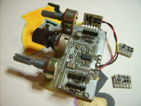
Figure 3: A discrete realized OTA-Overdrive-Cell, where all used Semiconductors got encircled (for a more detailed description, please refer to the text)
This means by the way, that I´ve been wondering on my own, of not gotten that idea longer before, to do the whole thing like this on the working principle of current sources, with a handful of electronic Parts and an OTA, and where I have been all times interested around music-electronics and hereby especially and mostly, on analog synthesizer circuits.
By the theme on analog synthesizers - as musical instruments - one is faced widely with OTA-Parts everywhere in the synthies, where the OTAs are needed for voltage controlled circuits, like VCOs and VCFs, and where is also often spoken about the circuit variations, what are using cascaded chains of "OTA-Cells", to implement some Audio-Functions, like Filter-IC´s, and so on.
And then came the question on the idea, why not also doing that on such an OTA-Cell for the functions of an Overdrive-, or a Distortion-Effect? Could this be a useful thing therefore?
(In Figure 3 you can see the simplified main OTA-Arrangement for the Overdrive-Project, with four basic Current-Mirrors - CM´s - arranged with some Transistors, a Differential Input Amp - dito, the very important Clipping-Diodes, and a JFET-Output-Buffer.)
For a first startup on that idea, I could not believe, that such a thing does not exist, by one or another of the well known manufacturers of Guitar-Stompboxes, maybe like Electro Harmonix, Ibanez, Boss, and so on, or maybe as a standard Overdrive-Effect and implemented into a Suitcase-Amplifier.
So, before a beginning on that technique some years ago, on such a Distortion-Device with an OTA-Cell, I wanted to search on the internet and I found much Overdrives, Distortion- and Fuzz-Boxes, and a lot of good guys and www.adresses, with tipps around the whole theme and a great living scene all around that, but nothing new, over the more and more told ideas and alltogether only the well known repeatings, since years - and each time with ICs as Opamps! (!! I got some good infos by Don Tillman, about there should be a few of the Gibson-Amps, with used CA3094-OTAs for the Distortion-Mechanisms, but as I think so, these also are working all with the Darlington-Buffers on the Diodes and this again means a usage on the effect, with not all the here told possible advantages, - but until up today, I did not find any of those Gibson-Schematics on the internet at all. I would be pleased, to get some of them - so if you know them, please give me some contributions!)
Also, there is on the Internet a lot of practice on Distortion-Circuits, wich all in common are using Opamps, where almost anytime the Clipping-Devices are configured as parts of the Signal Correction- and Feedback-Loops and spanned from the outputs to the negative inputs of the IC´s and quite often needing compensation capacitors.
But I could`nt find any such configuration, wich directly uses therefore an OTA. Then I googled "OTAs, Fuzz and Distortion", - but also nothing...
I wondered a little more and thought of the fact, that OTAs could be the wrong thing, of maybe not enough available current, with only 2 mA maximum realizeable with an OTA and where Opamps could give 20-50 mA and more, but on another look on existing circuits, they got less, so this could not be the problem. Until today, I haven´t got herefore any plausible answer to tell!
This guided all to the first ideas to some tests with the rare CA3080A-Devices in Metal-Cans. Then I tried some experiments with higher driven currents on the Clipping-Parts, hereby also with handmade and discrete implemented SIL6-OTAs and also one separate and very exotic version, with Zetex-Low-Sat Transistors in SOT-23 and 1:1 on a configuration like that circuit shown in Figure 3.
Headline Project Picture
Picture 2: First OTA-Overdrive-Version, implemented with a Quad-OP, a matched pair of AA118 Diodes and discrete SIL-06 OTA-Modules
Then, about two years ago, the core-functions were tested with several optimized units, also for good availability for needed parts from the manufacturers, and the resulting schematic was then implemented with almost three partly divided, main function blocks, where in the middle of the thing allways sits the said OTA-Cell and this will be later described by detail, down here in this publication.
In the meantime the CA3080s, and also some other OTAs, have fully gone obsolete, or they come only left to be very expencive on auction-offers and in the same expencive way are coming the directly followers to the CA3080-E in DIL08-Packages, the seldom NTE996. All these facts collected together - were unacceptable and this had to get fixed up with something useful, and not being too much expensive in the end!
So the schematic was changed again and the whole thing - until today - had to be implemented lately with the LM13700s from National Semiconductor (the manufacturing by the name is now gone to Texas Instr.), or as an alternative to this, with the NJM13600 from the japanese JRC, what are almost the same and very useful OTAs, too, and sometimes told for being better.
Although some voices on the internet are telling here, that all these amplifiers do not give by far the same Audio-Performance, as the good old CA3080A-Originals, made by RCA, or later coming from Harris, and then Intersil.
So, difficult to say if not tested, but the first obvious difference was about the CA3080-Chips, wich have being implemented with enhanced Darlington-Stages, as directly parts of the Current-Sources. They were made right until 1999, with some old machines on a very precisely developed Chip-Process from early 1967, formerly performed by RCA, where the National-Chips were developed (on just five minutes !!) later in the 70´ties and are using (only...) Standard-Wilson-Current-Mirrors. These IC´s are also told of being just designed for the fun and training of some students on creating some chips on somekind of likely a race, and almost only for testing a new design software for consumer electronics on wafer level.
See herefore the very interesting "LM13600/LM13700-Story" by Mr. Don Sauer on his very popular Internet-Publication at:
http://www.idea2ic.com/LM13700.html
(Over this link you will find a lot of information around the development of IC´s on the example of the LM13600/700´s, but always with some funny consequences around that case and getting almost perhaps only over a low-level-product, where I tend to plan a second variant to the project and with another, alternative solution, and maybe not using those chips!)
The here told facts are leading to assume for a fast, hasty development on that IC-Product. By these facts and on the above told race, this was also told around for saving some expencive semiconductor material (pure Silicon) with that manufacturing process and because of this, there could maybe come a little lack in the overall transparency on the Sound-Performance of the IC´s, mostly at fast transitions and with higher current levels, or perhaps on pulses, but in the end this is not known, before fully tested for that in all manner.
These IC´s seem therefore tending to be a really CAD-Design, from the playground of some Professors, with all the interests mostly on science... and with that in mind and the look between the lines, I personally would prefer for the realisation of this project unit on the NJM13600, coming from JRC (these are available from www.profusionplc.com at reasonable, good prices below 1 Euro!).
A real good advantage of the LM13700/NJM13600s is on the other hand, that they come as dual versions and are designed for stereo usage, so the overdrive-function could have been easily enhanced, with some needed features and what is also discribed later, down here in this publication.
4. The main Schematics as PDFs:
Maybe on the first look at the whole unit, the thing seems to be difficult, complicated and an overlarged circuit, especially when meant for beginners, but with some practice and engagement, one can easily get used to all parts of the device, at a "Step by Step" working. Therefore, one of the goals to the project is to give the DIY-Guitar-User a practical thing on hand, wich can be fixed in a few hours and wich can get handled to also an impressive "On Stage" used device. This all together, performed in a successive way to that product and with the possibility of learning much about the herefore used techniques and all the backgrounds to it, also in a Step-by-Step-Mode, individual and as wanted to, and in the end of coarse by hearing all that stuff.
The used parts are almost available standard electronics, wich are still present on the fast changing semiconductor market and here the still ongoing manufacturing and good availability of useful Germanium-Devices was another reason, to prepare such a unit to a realizeable, really enhanced DIY-Project, with enough headroom for also selfmade ideas and possible experimenting by the user in the future and also maybe to find some really new sounds on the effect, of coarse also by modifying the schematic!
I am telling here about a ready made project, but this describes still a smart unit as it is, and I keep also a lot of ideas in the background for an enhancement and as partly later to be described, for perhaps possible variations. This is meant also for the fact, that all OTA-ICs seem to get obsolete in the next coming years, as everyone can see, and what right in the moment happens also on the known production lines to the LM13700N.
So if they are cancelling now on these OTAs the devices in DIL16-Packages, then it is just a question of time, when the SO16´ers are going to follow, because the Industry accounts here only in millions on each cycle of an economic and commercially interested production line, for the made parts, so we can go on to wait, when these rules are cancelling product by product.
The production up today, runs here only on orders by means of "as is", and not on a "maybe", or a "perhaps", so if there won´t come enough orders, they will stop radically each production line, as to be seen widely on the aching companies for analog synthesizers and no one has therefore really good working alternatives, so by the way they are all telling, that the digital music-machines will be the future at all, but just on this very fact I tell here, that´s herefore only somekind of an emergency exit and this isn´t (!!), and right therefore, just take a look at the fast growing DIY-Scene for helping upon this misery and where here the most of the users prefer anytime mostly DIL-Devices, and no SMD parts for the ICs!
I am planning therefore to present for this case with the actual project somekind of a lifeaid, with a following project on a discrete OTA-Technique, but keeping this also just for the moment, or for longer in the background is needed to say and so to wait, what there happens in the next few months/years on the semiconductor market.
So to say, it is sadly maybe all ending in some innovations, wich maybe cannot get performed by the way, and what will happen, if the LM741 gets taken also out of the worlds markets, by running out of production?
As an optional addition onto the project, there could also follow a useful selection, or better told as the precisely matching of the semiconductors for such usages, but with not blowing the whole project to a big laboratory-action, because this jobs can be done quite accurately with a handful of additive electronic parts, prepared for a breadboard and almost performable with a good standard DVM.
5. No use of difficult to handle SMD´s and the usage of DIL-TL072-Opamps:
The first important fact for starting here the project for beginners on DIY, was strictly no usage of any problematic SMD´s for such a unit, with the possibility for an easy soldering the whole thing together and the usage of DIL-ICs on chooseable sockets.
Because of that, the unit gives the advantage, for to be called also as "Vintage" with actual TL072´s and what will be continued on (only maybe) a second kind of a version, that I will update in some days, with the possible availabilty of some really "Vintage by 1982 - TL074CJ - Black Top Opamps" in Cerdip-Packages, instead of the used low noise 2SK30A-Y/-GR JFET-Buffers. This is coming soon!
Also of coarse, the parts described here and used for the project will shurely go all obsolete sometime, as told above and seen very sadly in the last years - since 2005 - for the popular CA3080´s and then especially for the CA3280-OTAs, and other high-priority Synthesizer-ICs and where the whole Electro-Music-Community really got kicked by the Semiconductor Industry.
Because of these rules to the semiconductor market, there will be in the future a second published version of the unit (!! of coarse, only on enough feedback to this first one), fully prepared for SMDs, wich I will then update in full manner, but here for the first setting, is to start up with a valueable and for every small budget available unit in common and as one can see here. Another reason for implementing this Overdrive-Unit as SMD-Version is the pregnant factor of almost cheaper PCB-Space on double sided prints out of the production processes with vias, so the only single sided versions are coming as somekind of a speciality, or better let´s say herefore more seldom. That´s a hard reality, but quite actual, due to the mass productions of todays PCB´s!
6. Collected Facts on DIY-Benefits - Design-Goals for the published Project:
1.) Three makeable units (Sized as 52 x 100 mm, for all three variants) by two cuts, from one bought low-cost and single-sided Euro-Card, within the known standard dimensions of 100 x 160 Millimeters. This means, the project is well prepared for a Home-Concept and also as a Kitchen-Production for a whole Guitar-Group (and maybe with job-sharing), with almost a unique unit for each member, if you do not select the preferred Germanium Clipping Diodes, because this means, each unit will of coarse do the sounds a little different.
Smaller versions, with only some parts of the unit, can easily be upset and tested on a Expo-Strip-PCB (Vero-Board, Breadboard), for trying the thing in all parts, or maybe just for a tutorial. On a minimum-version, you´d need 1 OTA (also maybe CA3080, LM3080, NTE996), 2 Diodes and a N-Channel JFET.
2.) A variable and programmable Input-Pre-Amplifier, with a good sounding Lin-CMOS-OPAMP - the programmable TLC271 from Texas Instruments, for universal adaptive possibilities of various Pickups, or other Signal-Sources, but also easily interchangeable to the recommended usage of a High-Performance and High-Speed Excalibur-OPAMP, TLE2037 (= Burr-Brown OPA627-Equivalent, TLE2037C/SO-08 ca. 3,00 € at element14/Farnell) on the Input-Section, would be available by the usage of DIL08-SMD-Adaptors. Highly motivated readers of this publication could get supported on request, from my non-commercial and only private component-store with TLE2037A devices, on a email-demand!
3.) Realizable low power consumption thru the whole Signal-Chain, with three JFET-Buffers, for 9 Volt-Batteries, but also adaptive for 12 Volt or 15 Volt supplies, for maybe a planned usage as Synthesizer-Effect-Module inside of a Rack-Version. For the 2SK30A-GR JFETs I could give also some tipps, where you can get them - there are several (german) Distributors still offering them.
4.) Easy switchable effect between Silicon- or Germanium-Characteristics, with four interacting main control-potis, where the whole circuit environment gives enough possibilties to adjust all experimental changes, or maybe later needed dynamics. This is also important and nessesary, because of the possible, wide variations of different Germanium-Diodes.
5.) First additive overdrive ability on the amplification of the Input-Stage = a possible Pre-Amplifier-Clipping on a enhancement (OTAs are clipping a incoming Triangle-Wave into a nice Sine-Wave!). If the user knows how to set and change the functions, it is easy to modify all the parts of the circuit also for such special purposes, if needed to. This possible mode is only available by another additional, not implemented and not shown switch to the schematic! The Resistor R10 has therefore to be reduced on another value of 1 kOhms -10 kOhms and the Diodes need then to be disabled and replaced by a Resistor with 2 k Ohms, for example.
Figure 4: A sharp/edged Clipping by directly overloading the OTA-Inputs
6.) An additional and simple "Absolute-Value-Converter" and therefore a boostable Output-VCA, for additional Dynamic-Level-Control, dependent on the strength of the Guitar-Strike by the user. This part is also planned to be changed to an opamp-solution for a ABV on future enhancement within a implementation on a SMD-PCB-Layout. Here could also be the possibility of implementing an enhanced Compressor/Noise-Gate Stage on a control from a RMS-Converter. This means a really huge enhancement possibility.
7.) A really unique and easy control from a symmetrical to asymmetrical Clipping-Function and fully selectable Soft-/Hard-Characteristics on the effect, also with a volume-level-correction by the use of a Stereo-Dual-Potentiometer, where the user does not have to re-control all times the made changes of the characteristics to the levels on the external Poweramp.
Figure 5: A Symmetrical Soft-Clipping on the Overdrive for a Guitar-Signal
This is a very useful and really elementary control and could also be enhanced to the usage of a Pedal, with one of the Potis changed and optimized to a Foot-Controlling-Element.
Figure 6: An Asymmetrical Hard-Clipping on the Overdrive for a Guitar-Signal
8.) A real profit on the effect with "High-Leakage-Current Germanium- and Silicon-Parts", and additionally selected and matched Diodes, for a really true and very musically, smooth Semiconductor-Overdrive-Sound and therefore with no unexplainable magics in the backgrounds of the never understood blackbox. So the user knows, what he really can expect from the thing and what not.
Also here to say again: Highly motivated users of the device could get supported on request, by a non-commercial and only private component-store, with matched Germanium- and Silicon-Devices, on a email-demand! Explanations for selecting such parts will follow.
9.) Almost somekind of a really performed "Vintage Design" on all parts, with TO-92-JFETs, DIL-Packages and also for the PCB-Layout, with rounded wires and a software-generated Shield-Layer-Routing (Copper-Puring).
10.) All parts together are prepared for future enhancements and all times the project will be made for the user and not only for a product, with learning by hearing and doing, what in the end means overall fun and no educational stress to electronic beginners, as also to say, the first important thing you need herefore, is just to be interested...
Right here one could launch the phase on soldering that thing together, so take a look on the main circuit of the unit and then on the placeplan and let´s get the parts by some vendors.
If you want to use the proposed PCB, then no need to think, but if you decide to make your own construction onto a Vero-Board, do not shield the OTA-Section too much, because this could widely damp the sound radically on mostly the frequency ranges, due to parasitic capacities!
If you prefer shielding the thing additionally, with the benefits on blocking RF, then apply the shield until the resistors named R10/R13 and keep the inputs of the OTA-IC almost unshielded. Here is important to tell, that all my published PCB-Versions without the usage of SMD´s, will have the little disadvantage of being more sensitive to RF-Inducing, because of the larger and longer PCB-Wires (wich act like antennas). If you get in trouble with this fact, then a first solution to fix this problem, is to set the values of the input-dividing resistors for the OTAs downwards, from 220 Ohms onto 150 Ohms, and then setting up the amplification of IC 4, by increasing the value of R6 (for example from 22k to 39k, or 51k to 82k) respectively!
I hope this will not be nesessary anyhow, but the LM13700 ICs maybe will vary, and this also maybe on the NJM13600.
Discussie (7 opmerking(en))