
piRadio for FM Radio Receiver with RDS for Raspberry Pi [160520-1]
An app, specially for the rpi-receiver [160520] and a 3,5" touchscreen
For use with FM Radio Receiver with RDS for Raspberry Pi [160520]
Compatibility:
officially supported
- Raspberry Pi 2 , Raspberry Pi 3 ( including B+)
officially unsupported
- Raspberry Pi 1 and Raspberry Pi Zero
Downloads:
A Radio App for Linux , why yet another one?
Well, if you look around for Radio Apps you will soon find KRadio, Gnomeradio or RDS-Surveyer. Or you will find some TV-Apps that can also be used to listen to some radio. Every app has its strengths and weaknesses, but for use with IR-remote and touch display they all are beyond optimal. They were built with a desktop system, mouse and keyboard in mind. On a small 3.5” low resolution touch screen, they are hard to use, and without any kind of keyboard you may be lost.
The piRadio starts after boot automatically and restores the last settings. This is done with a script in the home folder of user pi. Also the autostart script for lxde has some additions to not even start the piRadio but also to disable the screensaver. You can find the autostart file for the current user in “~/.config/lxsession/LXDE-pi”. At the end you will see a line with “@sh /home/pi/startRadio.sh” , which tells to execute the script in “home/pi/startRadio.sh” after login. In the script “startRadio.sh” there are a few lines:
The UI is designed to work best with a 3.5” TFT with 480 * 320 pixels, like the Waveshare35a and controlled by a touchscreen or a IR-remote, also we added a small sample webpage to show how to control the app via a web browser. We developed the app using QT Version 5.10.1 and if you want to have a look inside, the app is open source and the code is provided under downloads.
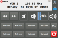
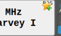
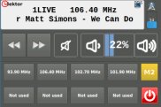
The display shows in the top right corner if we are receiving RDS information, the decoded station name will be added in front of the current tuned frequency. In the second line you will see the current text. If only the station name could be decoded, the display shows one line with a lager font for better readability. If no RDS information will be received only the current used frequency is displayed.

In the lower section you can see eight buttons which have the value “Not used” in the default configuration. This is the station memory, displaying eight buttons per page. With the M[x] button, here M1 currently, you can change the page that is displayed. In the default configuration you have four pages, meaning 32 station memories.
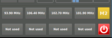
With the remote or keyboard you can access the station memory by pressing [xy] on the remote, where x is the station page and y the station number. For example to get the second station of the first page press 12, for the fourth station of the second page use 24. Page one is special as you don’t need to press the 1 first. If you just press 1 to 8 and wait for one second, the station stored in page 1 will be accessed. What if you use [0y] to access something. Well in this case you choose from the current page a station. If you grab a station memory that doesn’t exist, or has no station stored, the radio won’t change the frequency. As a side note, radio will display the currently selected page.
But if there are no stations stored how to do this? Well that is pretty simple, but only possible with the touch screen. Select the page you like to store the station by pressing the M[x] button as long as you arrive at the desired page. Afterwards hold the station button where you want to store the station for at least 5 seconds. In the display a bookmark star will appear to signal that the station is stored.
But it is inconvenient to change the frequency with the arrow keys. Sometime you want to tune directly to a known one. To do so there is an interface for the direct input. Just click on the display and you will get to the input mask for the frequency, on the remote use the “Menu” button, and on the keyboard it will be [E].
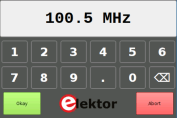
The current used frequency is displayed and you can simply starting typing a new one. For 98.55 Mhz just type [9][8][.][5[5] as at the first input the form will clear the Frequency. To start over just press the backspace button. If the Frequency you entered is in a valid range the “Okay” button will appear. If you are not satisfied with your choice you can click abort and be back to the main UI. To start over use the Backspace button, the Backspace key or on the remote the enter key. On the remote the A/B button is use to enter the decimal point. You can use “OK” on the remote to confirm the frequency.
At the right side is the bar graph with the little antenna Symbol, this is indicating the signal strength of the current channel. The the higher the value the better. To change the frequency you can use the forward and backward buttons, hold them for at least three seconds to start a seek upward or downward. On a remote use the fast forward or fast backward button or on the keyboard the left or right arrow. To step the frequency up or down use the arrow up or down.
To change the volume you can use the appropriate buttons, or mute and unmute with the mute key. On the remote this is volume plus , volume minus and mute, on the keyboard this is plus , minus and the M key.
Last but not least is the power button. If you click on it for more than 10 seconds you will see a little desktop icon in the upper right corner of the app display, else a simple shutdown will happen.
After you release the button a message window will appear and ask if you really want back to the desktop. If you click “yes” the application will close and you can access the desktop, else the message will close and the app will keep running.

The keymapping for the two UI elements used is as follows:
Key mapping for main window
Key mapping for frequency edit
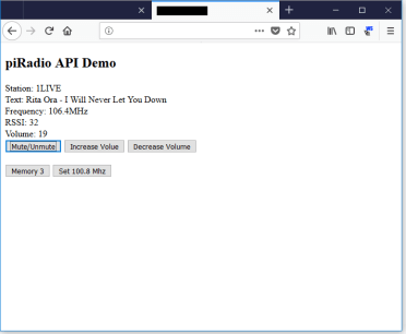
The websocket provides a way of getting data from the app and also send commands back. All data is exchanged in JSON, meaning that parsing can be done by the browsers javascript itself.
A small example with some Information and some interaction is provided a starting point. On the provided image a nginx is set up to provide a demo page. The code for the page can be found as download.
The advantage of a websocket connection is being bidirectional, meaning the server can activly send data to you . As with websocket you can use arbitrary types of data to be transmitted as it is up to you, to process them. The code provides some functions for handling the messages that come from the server, which currently are:
"VOLUME_UP”, "VOLUME_DOWN", "FREQUENCY_INC”, "FREQUENCY_DEC”, "SEEK_UP”, "SEEK_DOWN”, "MUTE_TOGGLE” . All this commands have no parameter. There are currently two commands that have parameter, these are "FREQUENCY_SET” with "Freq" for the desired frequency in 1/s (Hz) and "CHANNEL" with "Ch" for the desired channel. This gives you control over most of the basic functions.
A command without parameter is send with the following lines:
This will build an appropriate JSON string and sends it to the piRadio. For a command with parameter you can use the following:
This will set the frequency to 100.8 MHz on the piRadio. Note that the value must be a number and not a string. As JavaScript is not type safe you have to make somehow sure you don’t accidently use something else.
Besides commands you get new data from the piRadio. This includes the current frequency, volume, RDS Data as Raw Blocks and Raw Messages. Also you get the decoded radio text and station name and current signal strength reported. Messages are delivered with the following object keys: “VOLUME”, “RDS_STATION”, “RDS_TEXT”, “FREQUENCY”, “RSSI”, “RDS_RAW”, and “RDS_MESSAGE”. The RDS data allows you to develop your own decoder and decode the other messages the piRadio currently ignores. As an development environment an text editor for the web part and a browser for debugging is all you need.
In a further version of the software there may be more data and commands that can be modified. Also you can have a look at the websocket part in the radio itself and add missing features yourself. The source is available so feel free to play around with it.
If you connect with a browser to your pi, you’ll see a little demo page:
The LCD Screen
The Waveshare35 LCD is used in many of our projects. As setting it up to work shall not be “back magic”, we will show you how to get it running the fast way. You will need a few files for it, and if you are on windows, we need some extra Software. We will modify the SD-Card directly, at least for the boot partition. Here we need to store the “waveshare35a.dtb”. To retrieve it grab it from ‘https://www.waveshare.com/w/upload/3/34/LCD-show-180331.tar.gz’ and extract it. Copy the “waveshare35a-overlay.dtb” to “/boot/overlay/waveshare35a.dtb” on your SD-Card.
Now open up an editor ( on windows preferred notepad++) and edit the /boot/config.txt
Find the line with:
Now the SPI interface for the Display is active. That is what enables the hardware. We now need to modify some files inside the EXT4 Partition. As windows has no onboard tools for modifying these files, we need to boot the SD-Card now. In Linux this is much easier.
Behind the scenes:
These two files have been generated using some tools. Here we will show what the magic is inside.
The eassier part is the 99-fbturbo.conf. Here we simply changed the line :
The next step is to tell X11 how to handle the touchscreen. For this we use “40-libinput.conf” which has a few modifications inside. The touchscreen will work without this, but behave not as intended. The axis will be swapped and calibration not usable. Most of the older tutorials will tell to add parameter to the /boot/config.txt and to modify some X11 config files. With the newer approach we now need only to apply a so called transformation matrix. This matrix is generated with the tool xtcal ( https://github.com/KurtJacobson/xtcal ), you have to compile currently on your own. For the TFT we provide a solid basic calibration in landscape mode. To apply the settings look for the section :
To build xtcal you need some libraries on the pi and you have to use some console commands.
On the provided image for the piRadio you need to install the following additional packages:
You can easily hook an IR receiver up to your pi, the FM Radio Receiver with RDS for Raspberry Pi provides one. From the schematic you can see that the IR receiver is hook to pin 26. To get the receiver working we need a little help from the software side.
This is done with the help of LIRC ( Linux Infrared Remote Control ) and with some lines in the config.txt in /boot. To install lirc open a terminal and type “sudo apt install lirc” to get the required packages. To make the receiver working add the line “dtoverlay=gpio_ir,gpio_in_pin=26, gpio_in_pull=up” at the end of the file. This tells the pi to load the appropriate module and use pin 26 as IR input with pullup.
At this point LIRC is not working, and we need to change /etc/lirc/lirc_options.conf . We must edit the line with “driver” to “driver = default” and “device” to “device = /dev/lirc0” . At this point the basic steps are done, but LIRC has no idea what to do with the IR signals.
To do a short test, open a terminal and just stop lirc by “sudo /etc/init.d/lirc stop” and use mode2. With “mode2 -d /dev/lirc0” you will get the pulses the ir receiver detects. On a pi and with an remote using the rc-5 protocol it can look like this:
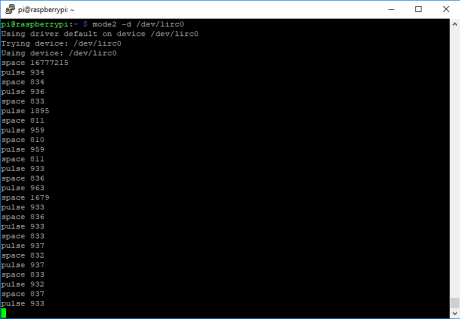
If you get something like this, you are good to go and the receiver at least sees your remote signals. But still LIRC has no idea what the pulses mean, currently they are just pulses. We need to provide LIRC an file which will tell it, what these pulses mean. We assume a RC-5 remote is used, as this has a standardized protocol.
We can grab the file from [http://lirc.sourceforge.net/remotes/rc-5/RC-5] and copy it to “/etc/lirc/lircd.conf.d/RC-5.lircd.conf”. This will tell LIRC how to handle the pulses from the remote. You may need to restart LIRC by “sudo /etc/init.d/lirc restart”. LIRC shall now “understand” what the remote is transmitting.
But this is only half way of getting the remote to work. To make things a bit more easy we setup the remote to simulate keyboard key presses. But for this we need another little helper, irxevent and a config file in our home folder. We can go to the home folder of the current user by typing “cd ~”. Here we need to add a “.lircrc” file which has the following layout :
The complete configuration ofthe piRadio for the image we build is already in place.
When it comes to UI development you try to use something that is supported on your device and also allows for easy development. Here the Qt Framework and its tools become handy. The Framework itself is multi-platform meaning you can find it on the major desktop OS, including Mac OS. Also on many portable devices witch run some kind of Linux or BSD flavored System Qt is most likely available. For the raspberry pi things even get better as we have already packages for Qt. Current version at the time of writing is Qt 5.10.1 with Qt 5.11 in beta. If you look at the packages provided for the pi, you’ll see the version indication 5.7.1, meaning a codebase around December 2016. As Qt evolves with new versions, fixes bugs or improve the hardware support, you like to have something more recent. This means building Qt fresh from source for the target and setting up a development environment.
This sounds a bit tricky and not something that you can do in your lunch break, and you are right. Preparing the pi and compiling the source on the pi would take a model 3 B+ up to 48 hours, if nothing went wrong. Also be aware that the pi during this time get pretty hot and may crash due to cheap power supplies.
To minimize the time it needs to compile the source and also have a convenient development environment you can do cross compiling. This means your PC will build something that the pi can execute. As this is far too large to be discussed here, this will be discussed in a different document.
To make it short, you can develop and debug your application on a PC with all the goodies and speed the machine offers, also compile it and let it automatically be loaded to the pi. Debugging will also be done over the network on your pc and use the pi to just execute the app you wrote, which is specially handy if you have only connected a small screen to the pi. This also is handy when working headless on a pi zero.

There is also an additional component, a WebSocket-server which can be used to build a Webinterface for the radio. Currently we don’t provide one, but have prepared the possibility to add one.
With this little set of modules in mind we can have a closer look at the audio part. We have a process that is moving samples from the audio input ( the tuner ) to the audio output ( here the class d amp).
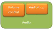
Also we have a part that is manipulating the audio level and dose the muting. As the audio loop is vital to the tuner operation, this is handled by a separate thread with highest priority, and tries to recover if something went wrong. Also we need a small buffer here ( 900ms) to give the system enough time to copy the data from the input to the output. If we don’t do this, we end up with stuttering spiund, as other processes on the system also take some CPU time. The volume control just accesses the ALSA-Mixer and sets the output volume level. A mute is done by setting the output to zero and meanwhile track the volume changes of the user internally.
Also you can query the capabilities of the tuner, which indicate with this hardware that we can get RDS information.
With this we can decide what information the tuner can provide, if it can seek to a new channel by its own or if it can provide RDS information, and in what format it is.
As all this is well defined in the API for the app it doesn’t really matter what kind of hardware you use, as long as it provides some basic functions. One note about the API, as some calls are blocking. If you do such a call, the function will take as long as the hardware does to process a given command or action. A Seek for example blocks as long as the tuner need to find the next channel. This is even true for reading RDS information. A read will be blocked as long as there is no new RDS information, and sometime with weak channels, this can take forever. Therefore some care must be taken, also retrieving RDS Information might not as simple as it sounds. So we take a look at how RDS is working and what data the tuner provides.
In the following we will use RDS for both RDS and RDBS. As you can see from the document RDS is far more than just the station name and the text you can see on your radio display. The RDS is an added service to the usual FM Broadcast and provides 1.187,5 Bit per second data rate. But the question is how to get the station and radio text at the end out of it. For this RDS provides some mechanism to put these information inside the DataStream. In the following we will make a short sprint through some basics.
RDS provides data blocks A to D ( or A to E for RDBS). Each block has 16 Bit payload and has a Block identifier in it, to distinguish between A, B, C, C’ and D. If you are lucky, your tuner and RDS subsystem already gives you the preprocessed blocks. With the rpi-receiver , the tuner provides RDS information in 3 bytes , an RDS block. Four blocks compose a RDS message, and we can have different message types with different information.
As you can see, we only get the data provided by the V4L API and need to collect them in the right order to build a message .To do this we need to get the messages A to D in a row. If due to bad signal conditions a block is missing, we need to start again.
Every message contains different information, e.g. the message 2A and 2B have information about the RDS Text and 0A and 0B about the station name. But one 2A or 2B message has only 2 or 4 characters of Text with a given position in it, but we can have up to 64 character for the radio text. This means after collecting the messages we also must collect the single character for the text.
This leads to a problem what to do if we should have received the text “elektor.radio music.” but due to some signal weakness only go “elek____radi________”, or even worse
“____tor.radio music.” . To detect that we got a new text there is a text A/B flag we use. If this flag changes we restart the collecting.
This has proven to work but the text is displaying not nicely in one peace, as we get character by character. On a display this means you don’t get the text as one peace and also while reading it, it is disturbing your eyes if the text suddenly extends or even starts scrolling. With the A/B flag the station signals which text “page” they are currently transmitting. Also some stations tend to just flip the “pages” , let’s say “Mac Guffin - plot device” to “Radio MacGuffin” , forth and back every some seconds. Also some stations don’t flip the text A/B flag at all and just send a new text, and make things even more complicated.
This gives a little headache to have a nice Text on the display. A few countermeasures were taken to address some of the issues that arose.
One is a separate buffer for the text A and text B “page”. If the flag now changes we don’t clear the buffer immediately, but used the one dedicated to the transmitted “page”. If we get a character on that “page” that differs from the one received before, we do a reset for that buffer. As long as the same text is received for the “page”, we can output the whole text we already received. This sometimes gives nice scrolling text, even with some weaker signal level.
The next countermeasure was to have a delay element for the text display. This enables us to collect during a period of two seconds more characters and may get a more complete text. This is done in the UI and not directly part of the RDS decoder.

This leads to the RDS text displayed with a two second delay, but with most complete text. The delay is for the user less of a problem than the suddenly expanding text. Also must be noted that the characters transmitted are not completely the same as in the ASCII charset. We must convert them with a few lookup tables to the characters from the ASCII table or even some utf8 ones.
The work done we would like to have avoided, as other projects already have implemented good to perfect decoding of many RDS messages. As these parts are ether specific to the app or not suitable for C++, or completely unmaintained. Therefore we decode only some very basic RDS information. Things like day of time and also additional program information are left out.
Besides this there are more messages that can be decoded, as seen in the RDS spec, but currently not handled within the code. If you are interested, the WebSocket interface provides you with the block and message data received.
Compatibility:
officially supported
- Raspberry Pi 2 , Raspberry Pi 3 ( including B+)
officially unsupported
- Raspberry Pi 1 and Raspberry Pi Zero
Downloads:
A Radio App for Linux , why yet another one?
Well, if you look around for Radio Apps you will soon find KRadio, Gnomeradio or RDS-Surveyer. Or you will find some TV-Apps that can also be used to listen to some radio. Every app has its strengths and weaknesses, but for use with IR-remote and touch display they all are beyond optimal. They were built with a desktop system, mouse and keyboard in mind. On a small 3.5” low resolution touch screen, they are hard to use, and without any kind of keyboard you may be lost.
The piRadio starts after boot automatically and restores the last settings. This is done with a script in the home folder of user pi. Also the autostart script for lxde has some additions to not even start the piRadio but also to disable the screensaver. You can find the autostart file for the current user in “~/.config/lxsession/LXDE-pi”. At the end you will see a line with “@sh /home/pi/startRadio.sh” , which tells to execute the script in “home/pi/startRadio.sh” after login. In the script “startRadio.sh” there are a few lines:
#!/bin/bash
killall irxevent
irxevent -d
/home/pi/piRadio -platform xcb
killall irxevent
irxevent -d
/home/pi/piRadio -platform xcb
The first one tells which command interpreter to use. The second kills all running irxevent and the third starts it again. The last line will execute the piRadio with the parameter “platform xcb” and tells Qt to use the X11 for displaying things as our desktop does. Another way with Qt can be to use OpenGL ( hardware accelerated graphics ) without interacting with the desktop. As we want to have a desktop app running aside everything else, we stay with the xcb approach.
The UI is designed to work best with a 3.5” TFT with 480 * 320 pixels, like the Waveshare35a and controlled by a touchscreen or a IR-remote, also we added a small sample webpage to show how to control the app via a web browser. We developed the app using QT Version 5.10.1 and if you want to have a look inside, the app is open source and the code is provided under downloads.
 |
 |
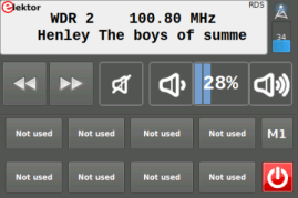
The display shows in the top right corner if we are receiving RDS information, the decoded station name will be added in front of the current tuned frequency. In the second line you will see the current text. If only the station name could be decoded, the display shows one line with a lager font for better readability. If no RDS information will be received only the current used frequency is displayed.
In the lower section you can see eight buttons which have the value “Not used” in the default configuration. This is the station memory, displaying eight buttons per page. With the M[x] button, here M1 currently, you can change the page that is displayed. In the default configuration you have four pages, meaning 32 station memories.
With the remote or keyboard you can access the station memory by pressing [xy] on the remote, where x is the station page and y the station number. For example to get the second station of the first page press 12, for the fourth station of the second page use 24. Page one is special as you don’t need to press the 1 first. If you just press 1 to 8 and wait for one second, the station stored in page 1 will be accessed. What if you use [0y] to access something. Well in this case you choose from the current page a station. If you grab a station memory that doesn’t exist, or has no station stored, the radio won’t change the frequency. As a side note, radio will display the currently selected page.
But if there are no stations stored how to do this? Well that is pretty simple, but only possible with the touch screen. Select the page you like to store the station by pressing the M[x] button as long as you arrive at the desired page. Afterwards hold the station button where you want to store the station for at least 5 seconds. In the display a bookmark star will appear to signal that the station is stored.
But it is inconvenient to change the frequency with the arrow keys. Sometime you want to tune directly to a known one. To do so there is an interface for the direct input. Just click on the display and you will get to the input mask for the frequency, on the remote use the “Menu” button, and on the keyboard it will be [E].
The current used frequency is displayed and you can simply starting typing a new one. For 98.55 Mhz just type [9][8][.][5[5] as at the first input the form will clear the Frequency. To start over just press the backspace button. If the Frequency you entered is in a valid range the “Okay” button will appear. If you are not satisfied with your choice you can click abort and be back to the main UI. To start over use the Backspace button, the Backspace key or on the remote the enter key. On the remote the A/B button is use to enter the decimal point. You can use “OK” on the remote to confirm the frequency.
 |
At the right side is the bar graph with the little antenna Symbol, this is indicating the signal strength of the current channel. The the higher the value the better. To change the frequency you can use the forward and backward buttons, hold them for at least three seconds to start a seek upward or downward. On a remote use the fast forward or fast backward button or on the keyboard the left or right arrow. To step the frequency up or down use the arrow up or down.
 |
 |
To change the volume you can use the appropriate buttons, or mute and unmute with the mute key. On the remote this is volume plus , volume minus and mute, on the keyboard this is plus , minus and the M key.
Last but not least is the power button. If you click on it for more than 10 seconds you will see a little desktop icon in the upper right corner of the app display, else a simple shutdown will happen.
After you release the button a message window will appear and ask if you really want back to the desktop. If you click “yes” the application will close and you can access the desktop, else the message will close and the app will keep running.
The keymapping for the two UI elements used is as follows:
Key mapping for main window
| Function | Keyboard Key | Remote Key | Remarks |
| Volume Up | + | Vol+ | |
| Volume Down | - | Val- | |
| Mute / Unmute | M | MUTE | |
| Power down | Q | POWER | |
| Frequency Up | Arrow Up | CH+ | |
| Frequency Down | Arrow Down | CH- | |
| Seek Upward | Arrow Right | TELETEXT RED | |
| Seek Downward | Arrow Left | TELETEXT BLUE | |
| Show / Hide Frequency Edit | E | MENU |
Key mapping for frequency edit
| Function | Keyboard Key | Remote Key | Remarks |
| Clear Frequency | BACKSPACE | ENTER | |
| Switch to sub MHz | Colon or Stop | A-B | |
| Set entered Frequency | ENTER | OK | |
| Abort and Close | ESCAPE or E | MENU |
Websocket API
The websocket provides a way of getting data from the app and also send commands back. All data is exchanged in JSON, meaning that parsing can be done by the browsers javascript itself.
A small example with some Information and some interaction is provided a starting point. On the provided image a nginx is set up to provide a demo page. The code for the page can be found as download.
The advantage of a websocket connection is being bidirectional, meaning the server can activly send data to you . As with websocket you can use arbitrary types of data to be transmitted as it is up to you, to process them. The code provides some functions for handling the messages that come from the server, which currently are:
"VOLUME_UP”, "VOLUME_DOWN", "FREQUENCY_INC”, "FREQUENCY_DEC”, "SEEK_UP”, "SEEK_DOWN”, "MUTE_TOGGLE” . All this commands have no parameter. There are currently two commands that have parameter, these are "FREQUENCY_SET” with "Freq" for the desired frequency in 1/s (Hz) and "CHANNEL" with "Ch" for the desired channel. This gives you control over most of the basic functions.
A command without parameter is send with the following lines:
…
var obj = { "COMMAND":"MUTE_TOGGLE" };
exampleSocket.send( JSON.stringify(obj) );
…
This will build an appropriate JSON string and sends it to the piRadio. For a command with parameter you can use the following:
…
var obj = { "COMMAND":"FREQUENCY_SET","Freq":100800000};
exampleSocket.send( JSON.stringify(obj) );
…
This will set the frequency to 100.8 MHz on the piRadio. Note that the value must be a number and not a string. As JavaScript is not type safe you have to make somehow sure you don’t accidently use something else.
Besides commands you get new data from the piRadio. This includes the current frequency, volume, RDS Data as Raw Blocks and Raw Messages. Also you get the decoded radio text and station name and current signal strength reported. Messages are delivered with the following object keys: “VOLUME”, “RDS_STATION”, “RDS_TEXT”, “FREQUENCY”, “RSSI”, “RDS_RAW”, and “RDS_MESSAGE”. The RDS data allows you to develop your own decoder and decode the other messages the piRadio currently ignores. As an development environment an text editor for the web part and a browser for debugging is all you need.
In a further version of the software there may be more data and commands that can be modified. Also you can have a look at the websocket part in the radio itself and add missing features yourself. The source is available so feel free to play around with it.
If you connect with a browser to your pi, you’ll see a little demo page:
For the hardwaresetup for the FM Radio Receiver
The LCD Screen
The Waveshare35 LCD is used in many of our projects. As setting it up to work shall not be “back magic”, we will show you how to get it running the fast way. You will need a few files for it, and if you are on windows, we need some extra Software. We will modify the SD-Card directly, at least for the boot partition. Here we need to store the “waveshare35a.dtb”. To retrieve it grab it from ‘https://www.waveshare.com/w/upload/3/34/LCD-show-180331.tar.gz’ and extract it. Copy the “waveshare35a-overlay.dtb” to “/boot/overlay/waveshare35a.dtb” on your SD-Card.
Now open up an editor ( on windows preferred notepad++) and edit the /boot/config.txt
Find the line with:
# dtparam=spi=on
and remove the first ‘#’ to set it to:
dtparam=spi=on
Now the SPI interface for the Display is active. That is what enables the hardware. We now need to modify some files inside the EXT4 Partition. As windows has no onboard tools for modifying these files, we need to boot the SD-Card now. In Linux this is much easier.
The Windows(r) way:
The pi must be connected to your network and you must know it’s ip address, also you must have ssh enabled,via raspi-config. You can find it under Interfacing options. Go to SSH and enable it. Now you can open WinSCP and do a connect to your pi. Put the files “40-libinput.con” and the “99-fbturbo.con” to a usb stick and mount it. Copy the provided “40-libinput.con” and the “99-fbturbo.con” to “/usr/share/X11/xorg.conf.d” as root. Unmount the USB-Stick and reboot the pi. The Desktop will appear on the LCD and touch will work.The Linux way:
Mount the SD-Card and copy the provided “40-libinput.conf” and the “99-fbturbo.conf” to “/usr/share/X11/xorg.conf.d” as root. Unmount the sd-card and put it back to the pi. If you now boot, you shall see the desktop on the tft and the touch shall work as expected.Behind the scenes:
These two files have been generated using some tools. Here we will show what the magic is inside.
The eassier part is the 99-fbturbo.conf. Here we simply changed the line :
Option "fbdev" "/dev/fb0 "
to
Option "fbdev" "/dev/fb1"
This will make the desktop appear on our tft screen on top of the pi, as we tell X11 to use the Frame buffer 1 instead of 0, being 0 the internal GPU and the 1 being the TFT.The next step is to tell X11 how to handle the touchscreen. For this we use “40-libinput.conf” which has a few modifications inside. The touchscreen will work without this, but behave not as intended. The axis will be swapped and calibration not usable. Most of the older tutorials will tell to add parameter to the /boot/config.txt and to modify some X11 config files. With the newer approach we now need only to apply a so called transformation matrix. This matrix is generated with the tool xtcal ( https://github.com/KurtJacobson/xtcal ), you have to compile currently on your own. For the TFT we provide a solid basic calibration in landscape mode. To apply the settings look for the section :
Section "InputClass"
Identifier "libinput touchscreen catchall"
MatchIsTouchscreen "on"
MatchDevicePath "/dev/input/event*"
Driver "libinput"
EndSection
In this section add the line :
Identifier "libinput touchscreen catchall"
MatchIsTouchscreen "on"
MatchDevicePath "/dev/input/event*"
Driver "libinput"
EndSection
Option "TransformationMatrix" "-0.003070 -1.113659 1.064514 1.118580 -0.004042 -0.077240 0 0 1"
This will apply to any touch point the screen reports the matrix and transform the coordinates to match with the desired pixel. If you rotate the screen you have to redo the transformation matrix. Using this matrix is the new way of doing a calibration.To build xtcal you need some libraries on the pi and you have to use some console commands.
On the provided image for the piRadio you need to install the following additional packages:
libxt-dev
libxxf86vm-dev
libxmu-headers
libxaw7-dev
libxft-dev
to use it open an terminal an type in the xtcal folder: ./xtcal -geometry 480x320. Please be aware that you must hide in LXDE the top bar in LXDE to get correct results. In the terminal you get the line to add to the “40-libinput.conf”.
libxxf86vm-dev
libxmu-headers
libxaw7-dev
libxft-dev
Adding an IR-Receiver to your Pi
You can easily hook an IR receiver up to your pi, the FM Radio Receiver with RDS for Raspberry Pi provides one. From the schematic you can see that the IR receiver is hook to pin 26. To get the receiver working we need a little help from the software side.
This is done with the help of LIRC ( Linux Infrared Remote Control ) and with some lines in the config.txt in /boot. To install lirc open a terminal and type “sudo apt install lirc” to get the required packages. To make the receiver working add the line “dtoverlay=gpio_ir,gpio_in_pin=26, gpio_in_pull=up” at the end of the file. This tells the pi to load the appropriate module and use pin 26 as IR input with pullup.
At this point LIRC is not working, and we need to change /etc/lirc/lirc_options.conf . We must edit the line with “driver” to “driver = default” and “device” to “device = /dev/lirc0” . At this point the basic steps are done, but LIRC has no idea what to do with the IR signals.
To do a short test, open a terminal and just stop lirc by “sudo /etc/init.d/lirc stop” and use mode2. With “mode2 -d /dev/lirc0” you will get the pulses the ir receiver detects. On a pi and with an remote using the rc-5 protocol it can look like this:
If you get something like this, you are good to go and the receiver at least sees your remote signals. But still LIRC has no idea what the pulses mean, currently they are just pulses. We need to provide LIRC an file which will tell it, what these pulses mean. We assume a RC-5 remote is used, as this has a standardized protocol.
We can grab the file from [http://lirc.sourceforge.net/remotes/rc-5/RC-5] and copy it to “/etc/lirc/lircd.conf.d/RC-5.lircd.conf”. This will tell LIRC how to handle the pulses from the remote. You may need to restart LIRC by “sudo /etc/init.d/lirc restart”. LIRC shall now “understand” what the remote is transmitting.
But this is only half way of getting the remote to work. To make things a bit more easy we setup the remote to simulate keyboard key presses. But for this we need another little helper, irxevent and a config file in our home folder. We can go to the home folder of the current user by typing “cd ~”. Here we need to add a “.lircrc” file which has the following layout :
begin
    prog = irxevent
    button = sys_00_command_11
    repeat = 3
    config = Key KP_Subtract CurrentWindow
end

begin
    prog = irxevent
    button = sys_00_command_01
    config = Key 1 CurrentWindow
end

begin
    prog = irxevent
    button = sys_00_command_02
    config = Key 2 CurrentWindow
end
Between a begin and an end we have the actions lirc shall take. For the button sys_00_command_11 this will be the execution of irxevent with the parameter Key KP_Substract CurrentWindow. This will send an “-“ Key to the currently running desktop app. The “repeat = 3” tells LIRC how to handle repeated key presses ( e.g. staying on the button). Here it lets every third received key press pass.The complete configuration ofthe piRadio for the image we build is already in place.
A short look on the software internals
Why the Qt Framework?
When it comes to UI development you try to use something that is supported on your device and also allows for easy development. Here the Qt Framework and its tools become handy. The Framework itself is multi-platform meaning you can find it on the major desktop OS, including Mac OS. Also on many portable devices witch run some kind of Linux or BSD flavored System Qt is most likely available. For the raspberry pi things even get better as we have already packages for Qt. Current version at the time of writing is Qt 5.10.1 with Qt 5.11 in beta. If you look at the packages provided for the pi, you’ll see the version indication 5.7.1, meaning a codebase around December 2016. As Qt evolves with new versions, fixes bugs or improve the hardware support, you like to have something more recent. This means building Qt fresh from source for the target and setting up a development environment.
This sounds a bit tricky and not something that you can do in your lunch break, and you are right. Preparing the pi and compiling the source on the pi would take a model 3 B+ up to 48 hours, if nothing went wrong. Also be aware that the pi during this time get pretty hot and may crash due to cheap power supplies.
To minimize the time it needs to compile the source and also have a convenient development environment you can do cross compiling. This means your PC will build something that the pi can execute. As this is far too large to be discussed here, this will be discussed in a different document.
To make it short, you can develop and debug your application on a PC with all the goodies and speed the machine offers, also compile it and let it automatically be loaded to the pi. Debugging will also be done over the network on your pc and use the pi to just execute the app you wrote, which is specially handy if you have only connected a small screen to the pi. This also is handy when working headless on a pi zero.
How the software and it’s components work
This splits the app in basically three parts, audio, radio and UI. Audio and radio can be seen as independent and are hold together by the UI.There is also an additional component, a WebSocket-server which can be used to build a Webinterface for the radio. Currently we don’t provide one, but have prepared the possibility to add one.
Also we have a part that is manipulating the audio level and dose the muting. As the audio loop is vital to the tuner operation, this is handled by a separate thread with highest priority, and tries to recover if something went wrong. Also we need a small buffer here ( 900ms) to give the system enough time to copy the data from the input to the output. If we don’t do this, we end up with stuttering spiund, as other processes on the system also take some CPU time. The volume control just accesses the ALSA-Mixer and sets the output volume level. A mute is done by setting the output to zero and meanwhile track the volume changes of the user internally.
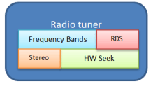
Radio tuner
The other part, the radio tuner is basically very simple to control, but there are some hurdles to take care of. If you look at the V4L bindings from RDS-Surveyor, the interface is straight forward when it comes to open the device and controlling it. But with the frequency settings and modulation it gets a bit tricky. The tuner provides the frequency ranges it supports, also the type of modulation, and currently with this hardware you must take care not to tune something that is out of band.Also you can query the capabilities of the tuner, which indicate with this hardware that we can get RDS information.
With this we can decide what information the tuner can provide, if it can seek to a new channel by its own or if it can provide RDS information, and in what format it is.
As all this is well defined in the API for the app it doesn’t really matter what kind of hardware you use, as long as it provides some basic functions. One note about the API, as some calls are blocking. If you do such a call, the function will take as long as the hardware does to process a given command or action. A Seek for example blocks as long as the tuner need to find the next channel. This is even true for reading RDS information. A read will be blocked as long as there is no new RDS information, and sometime with weak channels, this can take forever. Therefore some care must be taken, also retrieving RDS Information might not as simple as it sounds. So we take a look at how RDS is working and what data the tuner provides.
RDS and why everybody needs to reinvent the wheel
The RDS ( Radio Data Service) , in Europe, or the RDBS ( Radio Broadcast Data System), in the States, is a System to transmit digital data along with a FM broadcast. For the RDS you can find the specification on [http://www.interactive-radio-system.com/docs/EN50067_RDS_Standard.pdf].In the following we will use RDS for both RDS and RDBS. As you can see from the document RDS is far more than just the station name and the text you can see on your radio display. The RDS is an added service to the usual FM Broadcast and provides 1.187,5 Bit per second data rate. But the question is how to get the station and radio text at the end out of it. For this RDS provides some mechanism to put these information inside the DataStream. In the following we will make a short sprint through some basics.
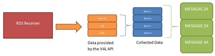
RDS provides data blocks A to D ( or A to E for RDBS). Each block has 16 Bit payload and has a Block identifier in it, to distinguish between A, B, C, C’ and D. If you are lucky, your tuner and RDS subsystem already gives you the preprocessed blocks. With the rpi-receiver , the tuner provides RDS information in 3 bytes , an RDS block. Four blocks compose a RDS message, and we can have different message types with different information.
As you can see, we only get the data provided by the V4L API and need to collect them in the right order to build a message .To do this we need to get the messages A to D in a row. If due to bad signal conditions a block is missing, we need to start again.
Every message contains different information, e.g. the message 2A and 2B have information about the RDS Text and 0A and 0B about the station name. But one 2A or 2B message has only 2 or 4 characters of Text with a given position in it, but we can have up to 64 character for the radio text. This means after collecting the messages we also must collect the single character for the text.
This leads to a problem what to do if we should have received the text “elektor.radio music.” but due to some signal weakness only go “elek____radi________”, or even worse
“____tor.radio music.” . To detect that we got a new text there is a text A/B flag we use. If this flag changes we restart the collecting.
This has proven to work but the text is displaying not nicely in one peace, as we get character by character. On a display this means you don’t get the text as one peace and also while reading it, it is disturbing your eyes if the text suddenly extends or even starts scrolling. With the A/B flag the station signals which text “page” they are currently transmitting. Also some stations tend to just flip the “pages” , let’s say “Mac Guffin - plot device” to “Radio MacGuffin” , forth and back every some seconds. Also some stations don’t flip the text A/B flag at all and just send a new text, and make things even more complicated.
This gives a little headache to have a nice Text on the display. A few countermeasures were taken to address some of the issues that arose.
One is a separate buffer for the text A and text B “page”. If the flag now changes we don’t clear the buffer immediately, but used the one dedicated to the transmitted “page”. If we get a character on that “page” that differs from the one received before, we do a reset for that buffer. As long as the same text is received for the “page”, we can output the whole text we already received. This sometimes gives nice scrolling text, even with some weaker signal level.
The next countermeasure was to have a delay element for the text display. This enables us to collect during a period of two seconds more characters and may get a more complete text. This is done in the UI and not directly part of the RDS decoder.
This leads to the RDS text displayed with a two second delay, but with most complete text. The delay is for the user less of a problem than the suddenly expanding text. Also must be noted that the characters transmitted are not completely the same as in the ASCII charset. We must convert them with a few lookup tables to the characters from the ASCII table or even some utf8 ones.
The work done we would like to have avoided, as other projects already have implemented good to perfect decoding of many RDS messages. As these parts are ether specific to the app or not suitable for C++, or completely unmaintained. Therefore we decode only some very basic RDS information. Things like day of time and also additional program information are left out.
Besides this there are more messages that can be decoded, as seen in the RDS spec, but currently not handled within the code. If you are interested, the WebSocket interface provides you with the block and message data received.
Want to build a project?
Bring your design to life with the Elektor PCB Service, powered by Eurocircuits. Upload the project files and order professionally manufactured PCBs or assembled boards through a proven European production platform.
Supporting KiCad, Eagle, Gerber, and ODB++ formats, the service is suitable for everything from prototypes and validation builds to series production and volume manufacturing.
Made in Europe. Fast. Reliable. Professional.
Discussie (3 opmerking(en))