
Raspberry Pi Wobbulator / 130484-I
A wobbulator (or sweep generator) is a piece of test equipment which is used in conjunction with an Oscilloscope to measure the frequency response characteristics of a circuit. It uses a “ramp” or “sawtooth” function generator connected to a Voltage Controlled Oscillator (VCO) to produce an output sweep over a defined range of frequencies.
A wobbulator (or sweep generator) is a piece of test equipment which is used in conjunction with an Oscilloscope to measure the frequency response characteristics of a circuit. It uses a “ramp” or “sawtooth” function generator connected to a Voltage Controlled Oscillator (VCO) to produce an output sweep over a defined range of frequencies. The response characteristics of the circuit under test can then be displayed on an Oscilloscope. A wobbulator is a useful tool for aligning the intermediate frequency (IF) stages of superhet receivers, but can also be used to measure the frequency response characteristics of RF filters and other circuits.
The Raspberry Pi Wobbulator implements the functionality of a conventional wobbulator by using a Raspberry Pi, a Direct Digital Synthesizer (DDS) module and an Analogue to Digital Converter (ADC) module. The Raspberry Pi’s General Purpose Input Output (GPIO) interface is programmed to control the DDS module to generate the frequency sweep and to communicate with the ADC module to measure the response of the circuit under test. The Graphical User Interface (GUI) allows the user to choose the parameters for the frequency sweep and also displays the results.
Python 3 source code for the Raspberry Pi Wobbulator software is also available at https://github.com/mi0iou/
Read my Raspberry Pi blog at http://www.asliceofraspberrypi.co.uk
Talk to me on Twitter @TomHerbison
UPDATE
As a "spin off" of this project I've written some code so that the DDS module can be used with the Raspberry Pi on its own as a very cheap and simple RF signal generator. Screen shot of RF signal generator uploaded
Python 3 source code available at https://github.com/mi0iou/
UPDATE
Details of the how to connect the ADC Pi module to the Raspberry Pi are now on my blog, which includes a detailed "how to" for setting up i2c on the Raspberry Pi.
UPDATE
Circuit diagram and photo of prototype Buffer Amplifier / Detector uploaded. Full details have been posted on my blog.
UPDATE
Some more screenshots of Raspberry Pi Wobbulator in action have been uploaded. I used it to test some bandpass filters for a transceiver I'm working on. The prototype performed very well over a wide range of frequencies.
UPDATE
Trying to get to grips with DesignSpark PCB software to design a PCB for the Raspberry Pi Wobbulator.
UPDATE
Yahoo group set up for those interested in the design, construction and use of the Raspberry Pi Wobbulator
UPDATE
Design of the Raspberry Pi Wobbulator PCB is in progress. Click on the link below for a progress report:
UPDATE
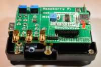
The Raspberry Pi Wobbulator prototype has been revised to incorporate an onboard ADC chip and and onboard Logarithmic Amplifier (instead of an external Buffer Amplifier / Detector stage). Full details of how the design was developed are available on my blog:
Photos of the revised Raspberry Pi Wobbulator prototype have been uploaded along with a screenshot of the revised prototype being used to examine the frequency response of a RF crystal with and without a small capacitance in parallel.
UPDATE
The Raspberry Pi Wobbulator software has been revised in line with the changes made to the hardware. The number of user selectable input channels has been reduced from 8 to 4 as a consequence of going over to the onboard ADC chip, and a user selectable "Bias compensation" option has been introduced.
The revised source code is available on GitHub (but I have also uploaded it here) and I've uploaded a screenshot of the revised software which demonstrated the effect of selecting the "Bias" option. The two red plots are without the "Bias" option and the two blue plots are with the "Bias" option. More details to follow shortly.
UPDATE
Please see my latest blog post for a detailed explanation of the new "Bias compensation" feature introduced in version 1.1 of the Raspberry Pi Wobbulator software.
UPDATE
Proposed schematic for the Raspberry Pi PCB has been uploaded (file name "RPi_Wobbulator_schematic.png"). This schematic is available for download under 'Attachments' below or directly by clicking here.
I'd welcome any comments on (or corrections to) the proposed schematic because I'm currently putting the finishing touches to the PCB layout, and once this is completed I will be placing an order for a batch of PCB's to be manufactured.
UPDATE
PCB design has been finalized and uploaded. You can find the file under Attachments below or download it directly by clicking here.
An order has been placed for an initial batch of PCB's.
UPDATE
I'm eagerly awaiting delivery of the initial batch of PCBs, and I've been working on putting together a kit of components to go with the PCB at the best price possible.
UPDATE
There was a small error on the schematic, but fortunately this was picked up before the PCB layout was completed. An amended schematic has now been uploaded.
PCB's are currently in transit, so hopefully will be delivered very soon.
UPDATE
I'll be posting full assembly instructions on my blog shortly, but in the meantime if anyone is interested in obtaining one please visit:
Seasons greetings to one and all.
UPDATE
First batch of Raspberry Pi Wobbulator PCBs and kits have been shipped, and the first part of my step-by-step assembly guide has been published on my blog:
UPDATE
Second (and final) part of my step-by step assembly guide containing full instructions for building the Raspberry Pi Wobbulator from the PCB and component kit has just been published on my blog:
Instructions for setup and testing will follow soon.
UPDATE
I've added a couple more photos of the fully assembled RPi Wobbulator. Also the first part of the setup and testing guide, which deals with setting the Raspberry Pi up to use I2C, has just been published on my blog.
UPDATE
Parts 2 and 3 of the setup and testing guide for the Raspberry Pi Wobbulator are now on my blog:
And other users who have built the kit have been sharing details of their experiences on the Raspberry Pi Wobbulator Yahoo group:
If you are interested in getting your hands on a kit please visit:
And I've uploaded some more screenshots.
UPDATE
The RPi Wobulator software has been updated! The RPi Wobbulator now continuously repeats the frequency sweep until the user clicks on the "Stop" button, instead of performing a single sweep. The seed at which the sweep is performed has also been increased by a factor of x10 by adjusting the ADC chip parameters. Thanks to Tony Abbey for contributing to the project and implementing these changes. This collaboration was made possible by GitHub
The new software is available on GitHub but I've also uploaded a .zip archive containing the new software here. You can find the file under Attachments below or download it here directly (login required).
A screenshot showing the new software in action has also been uploaded.
UPDATE
The RPi Wobbulator software has now been updated again, mostly thanks to Tony Abbey, who has joined the project. An option has been added to clear the display screen after every sweep and the trace is now displayed in real time while the sweep is taking place. Another option has been added which when selected, runs the ADC chip at full speed with 12 Bit resolution. Finally the code has been altered to display the "Grid" by default, however it can still be removed by deselecting the check box.
A screenshot showing the new software in action has also been uploaded.
For all the latest news and user feedback please visit the RPi Wobulator Yahoo Group:
UPDATE
Development of the RPi Wobbulator software has continued with contributions from a number of project members. The following features have been added:
- Frequency and Voltage labels
- X and Y Scales
- Sweep settings now saved in a parameter file
- User menus
- K(Hz) and M(Hz) conversion
- User description panel
- Single sweep option
- Option to display Y axis in Volts or dBm
A couple of screenshots showing the new software in action have also been uploaded.
For all the latest news and user feedback please visit the RPi Wobulator Yahoo Group:
UPDATE
The RPi Wobbulator software has been updated, now with improved Y axis scales and auto selection of linear scale when channel 1 (linear detector) is selected.
A couple of screenshots showing the new software in action have also been uploaded.
For the very latest updates and discussions please visit the RPi Wobbulator Yahoo group.
UPDATE
The RPi Wobbulator software has been updated. Resolution (and hence sample rate) of the ADC is now user selectable. The dBm Y scale for channel 2 has been expanded to make better use of the available space, and the user interface has been simplified with the removal of the "dBm and "Bias" options. The dBm scale is now used only for channel 2 (the logarithmic detector) and the bias compensation algorithm is only applied to channel 2 so that the dBm scale gives a true reading. For Channel 1 (the linear detector) the volt Y scale is used and bias compensation is not applied so that the volt scale is accurate.
A screenshot showing the new software, showing the expanded dBm scale has been uploaded.
For the very latest updates and discussions please visit the RPi Wobbulator Yahoo group.
Discussie (1 opmerking(en))