
VGA autonomous console
How to debug on serial without a PC ? How to replace the 2x16 LCD on small systems ? With a VGA autonomous console !
How to debug on serial without a PC ? How to replace the 2x16 LCD on small systems ? With a VGA autonomous console !
I don't know for you, but everyday, I have to read some debug messages from electronic cards. Most of the times, I turn-on my computer, launch a terminal, and connect a serial adapter (or in a different order :) ). This project has two main goals : to create an autonomous console, and to play with the elektor FPGA card.
- 06 may 2014 : Unit test of UART available. Source here.
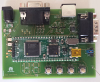
Here, the second prototype with a "real" PCB :

The "must have" of a terminal is an ASCII-art splash screen ! Here the first version :

Here, the first prototype (named r0.1) using breadboard and long wires :) :

When you look at the VGA signal specifications, it seems quite simple to produce an image, isn't it ? In the traditional approach of a hobbyist, you look for an µC, here is the first problem ... Which one should you choose ? Big µC have sometimes display controllers, but a complex (and expansive) component for a so simple application is a shame. You can also imagine to produce VGA signals by bit banging on GPIOs, but the time between two pixels is very short, typically less than 20ns (pixel clock is 50MHz for 800x600). So, most of the CPU can't produce them. The final way is to use a dedicated component, like Solomon Systech chips, it's a good solution, but not fun for a shadock electronician. By the way, dedicated logic functions are synthesizable by PLD components, and Elektor has recently released an FPGA card, so let's try and use it !
Figure 1 show the block diagram of the project.

As you can see there are two different blocks to control the display. The first, named VGA controller will produce clock signals (HSync and VSync) and synchronize data to them. The second is used to create bitmap image from ascii codes of characters received by UART.
One important thing to remember is that monitor must permanently be refreshed, so datas must be stored into memory. At this point you get a choice : create character image only when byte is received and save the whole screen image into memory, or save the characters and produce there image on the fly. This two solutions modify : the size of the memory, the power consumption, and the size of the VGA clock domain into the PLD.
In the next paragraphs i will explain the job of each parts. All the logical functions are located into the FPGA, so all of the “IP” below are into the Spartan chip ! Only at the end i will come back to electronic board around the Elektor FPGA module.
VGA controller IP
With technology's constant evolution, size of screens is increased every 2 or 3 years (see Barry Hendy papers on “Pixels per dollar”). The old VGA resolutions has been forgotten and new names has been created : SVGA, VESA, XGA ... But, signals models were kept until recently. You can show examples of standard resolutions into table 1.
For this project, i have chosen 800x600@72Hz because 50MHz of pixel clock can be get from standard oscillator, and the spartan 3 of the FPGA card works fine at this frequency. On figure 2, you can see a detailed diagram of the IP.
 | Size | Refresh rate (Hz) | Revision | Pixel clock (MHz) |
| 640x480 | 70 | VGA | 25,175 | |
| 640x480 | 60 | VGA | 25,175 | |
| 800x600 | 75 | SVGA | 49,5 | |
| 800x600 | 72 | VESA | 50 | |
| 1024x768 | 60 | XGA | 65 | |
| 1280x1024 | 60 | VESA | 108 | |
| 1600x1200 | 60 | VESA | 162 | |
| 1920x1200 | 60 | VESA | 193,16 | |
| 1920x1440 | 75 | VESA | 297 |
The Hsync and Vsync blocks are made with counters based on clock signal. This IP considers that his input clock is the pixel clock, so for my example : 50MHz. To allow readers of this article to change the resolution, all the timings can be changed by parameters (see table 2) for front and back porch, pulse length, etc. At the reset, values of each parameter is used to compute the abolute number of clock cycle of each event. Example : Hsync pulse is asserted after H_FP clocks(front porch), and is de-asserted after H_FP + H_PULSE clocks (front porch + hs length). This is not an optimal way, but as this the HDL code is more simple.
To allow VGA memory addressing or, in this case for the character generator, two counters give the current X and Y refresh position on the screen. They are incremented when the “spot” is inside the displayable region, also reported by valid_o signal.
Last but not least, a small buffer is inserted between pixels_i (data input) and r/g/b outputs. Color signals must not be toggled at risk of loosing sync. So, red_o, grn_o and blue_o are pulled low when “valid” signal is unasserted.
On the attached file r01_vgac.zip, you can found the IP and a testbench using icarus verilog and gtkwave. Figure 3 show a short example of the simulation result.

/* Next chapter coming soon :D */
Build This Project
Bring this design to life with the Elektor PCB Service, powered by Eurocircuits. Upload the project files and order professionally manufactured PCBs or assembled boards through a proven European production platform.
Supporting KiCad, Eagle, Gerber, and ODB++ formats, the service is suitable for everything from prototypes and validation builds to series production and volume manufacturing.
Made in Europe. Fast. Reliable. Professional.
Discussie (3 opmerking(en))