
Wi-Fi / Bluetooth / USB shield for Arduino & Platino (120306)
Today all & sundry, devices included, have to be “connected”, 24/7, all year round. You may have a Facebook account, but what about your oscilloscope? Does your multimeter tweet enough? Is your soldering iron linked in? You may be a non-communicative nerd but your bench power supply may be craving for social interaction.
PCB, bare, 120306-1
Module WizFi220 Serial to WiFi Module (High TX Power), 130076-92
FT232R USB/Serial Bridge/BOB, 110553-91
Platino PCB, bare, 100892-1
FTDI USB-to-TTL converter cable 5V, 080213-71
FTDI USB-to-TTL converter cable 3V3, 080213-72
Hello community,
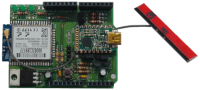
I am working on an Arduino shield on which you can either mount a Wi-Fi module or a Bluetooth module controlled through a serial port. Since these modules often have to be configured with a PC before you can use them comfortably, the shield also includes a USB serial port that allows connecting them directly to a PC. After configuration you can give control of the wireless module to the MCU.
The shield can also be used to add USB to Platino. The shield is compatible with the standard FTDI cable and with the Elektor FTDI Break-out Board (BoB).
A 3V3 power supply and a couple of level shifters complete the shield.
If all you need is a wireless module then the shield can even be used without Arduino.
Regards,
Clemens
Update June 5, 2012
The prototype PCB has to be corrected because the Bluetooth module is hindered by the Arduino Uno's USB connector. Also messed up the BT RS-232 connection because I labeled them incorrectly in Eagle. Bummer, now I have to correct the PCB :-(
I attached the schematics below, I hope you can read them.
Update June 12, 2012
The PCB has been corrected, it is attached below.
Update August 1, 2012
I have finally come around to finish this project. The PCB has been updated and is now a real rectangle. I also added a jumper to be able to disconnect the 3V3 rail from the Arduino connector. Also R8 was moved slightly to the side to leave a bit more space for Arduino's USB connector.
Article writing is in progress and its publication is scheduled for Elektor's October edition.
The project files below have been updated.
I still should finish the software part, but time is a problem. Below you will find what I came up with so far. I was stuck on the binary transmission part using escape sequences, but most other functions work. Note that it has FreeRTOS typedefs in it, but they can be easily replaced with other types.
PCB, bare, 120306-1
Module WizFi220 Serial to WiFi Module (High TX Power), 130076-92
FT232R USB/Serial Bridge/BOB, 110553-91
Platino PCB, bare, 100892-1
FTDI USB-to-TTL converter cable 5V, 080213-71
FTDI USB-to-TTL converter cable 3V3, 080213-72
Want to build a project?
Bring your design to life with the Elektor PCB Service, powered by Eurocircuits. Upload the project files and order professionally manufactured PCBs or assembled boards through a proven European production platform.
Supporting KiCad, Eagle, Gerber, and ODB++ formats, the service is suitable for everything from prototypes and validation builds to series production and volume manufacturing.
Made in Europe. Fast. Reliable. Professional.
Discussie (3 opmerking(en))