
Analog Synthesizer Filter using one opamp
Lowpassfilter with voltage controlled frequency and Q (up to oscillation). Runs on single supply 5V and can be sweeped from 16kHz to 30Hz with a 0 to 5V control voltage. The circuit uses only one opamp chip together with some passive components. In the described circuit this frequency tuning follows an exponential control curve over 9 octaves. The single 5V operation makes the filter very suitable to be combined with a microcontroller.
Circuit concept:
Almost every filter is using components like capacitors or inductors, this one is not. This one uses a specific opamp feature found on a few models that is called "adjustable supply current" (these opamps have a dedicated pin for that). By tuning this current over a wide range the bandwidth of the opamp model I found could be changed from 100kHz down to 10Hz (limited to 16KHz-30Hz in the final circuit) . Those of you that have some knowledge on old synthesizer circuits might know that the 1982 Russian PoliVoks synthesizer used this trick also. The circuit described here is completely different, simpler (uses 1 available opamp instead of 3 obsolete opamps) and adds voltage controlled Q. This simple/cheap filter circuit is attractive for a (future project) monophonic and even polyphonic synthesizer design because scaling up to n voices needs n filters so the simpler they are the better.
You can find a complete synthesizer design using this filter circuit here:
https://www.elektormagazine.com/labs/synthesizer-monovoks4-analog-filter-polivoks-style
To explain the circuit, both a basic schematic is attached (named: filter basic) using dual +/2V5 supply and the final version with voltage controlled Q up to (sinewave) selfoscillation running on single +5V/0 supply.
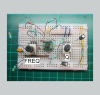
Both versions are build and pictures of the breadboard versions are shown.
A detailed document "AnalogSynthfilter-Ts271" describes the circuit and shows scope measurements on the filter settings. A soundexample "LeftFilterOut-RightFilterIn" is present of the filter sweeping with a simple static sawtooth as input wave.
Components:
The opamp used is a very specific one but it is in active production and available (50 cent) from several distributors like Digikey, Mouser and RS-components.
It should be the TS271 from manufacturer STMicroelectronics (and not the TLC271 or likewise chips from other manufacturers).
I build over10 circuits using different versions of this chip like SOIC packages TS271IDT (industrial) TS271CDT (commercial) and the now obsolete DIP package TS271CN. They all work fine and have quite identical performance.
I also tested the TLC271 (Texas Instruments) and that model does NOT work here, although some sellers tell you it is the same chip, it is not for this purpose.
Remarks/Limitations/Suggestions:
The tuning voltage and Q control ranges are inverted, means that 0V gives 16kHz and 5V gives 30Hz. When using microcontroller DAC control this is not an issue but otherwise you need an opamp inverter circuit to flip this.
This is not a "HIFI" quality filter for measuring purposes but a circuit for a synthesizer application. Especially at resonance it adds slewrate distortion (this gives a growling sound but no harsh clipping) and the suppression above the cutt-off frequency is somewhat limited.
The exponential control may not be precise enough to make it an exactly pitched tunable oscillator but it is good enough for a tracking filter and makes it possible to get wide range control using a linear DAC. Audio input signal levels should be kept below 80mVpp in (giving 320mVpp out) to prevent increasing slewrate distortion but if you like the overloading behaviour you can go up to Volts without problems.
This is an analog circuit, the filter frequency is quite dependant on supply voltage. All measurements used a 5.00V supply. That is not what you usually get from a USB port..
Output load resistance should be 10kohm or more, if you want to hook up your active PC-speakers put a 10kohm in series and keep levels low as this circuit can be set to oscillate from 30Hz to 15kHz.
Status:
Two breadboard versions of this circuit have been build, several TS271 opamp versions have been tested.
The same opamp has been used by me in earlier synth designs using somewhat different filtercircuits. The circuit described here is the next improved implementation of a filter using this TS271 opamp.
Building it:
This circuit is shown on breadboard but. a PCB is designed for a complete monophonic synth with analog signal path using this filter.. This synth, named "MonoVoks4" can also be found on the Elektor lab. As mentioned, the compact design will be an attractive candidate for a polyphonic synth also.
For the pro's: (see attached document)
The lowest Q setting still gives a slight peak in this circuit, if you want a really damped response then change the 10kOhm load "pull-up" resistor at the output of the opamp to a "pull-down" resistor. Drawback is that high Q values and selfoscillation are not possible then. To have both you could hook up the resistor to a switch or microprocessor I/O pin and flip state (but you get a short audioclick when flipping that).
The reason for this dc-loadflip to work as a damping changer is that the output stage of the TS271 is not symmetric. The datasheet shows the inners of the chip output stage. Looking into the chip: delivering (=sourcing) current comes from a low impedance FET-source output, but sinking current is a done with a high impedance drain output having a feedback capacitor. So having the output stage sinking dc current leads to more phaseshift in the feedback loop. This is also related to how the voltage controlled Q works. In the circuit design 2 diodes are used as dc-current controlled variable (ac) resistor to change circuit loopgain and thereby change the damping of the filter.
More information on synth designs using this opamp and example sounds can be found on my personal website: www.rs-elc.nl
Almost every filter is using components like capacitors or inductors, this one is not. This one uses a specific opamp feature found on a few models that is called "adjustable supply current" (these opamps have a dedicated pin for that). By tuning this current over a wide range the bandwidth of the opamp model I found could be changed from 100kHz down to 10Hz (limited to 16KHz-30Hz in the final circuit) . Those of you that have some knowledge on old synthesizer circuits might know that the 1982 Russian PoliVoks synthesizer used this trick also. The circuit described here is completely different, simpler (uses 1 available opamp instead of 3 obsolete opamps) and adds voltage controlled Q. This simple/cheap filter circuit is attractive for a (future project) monophonic and even polyphonic synthesizer design because scaling up to n voices needs n filters so the simpler they are the better.
You can find a complete synthesizer design using this filter circuit here:
https://www.elektormagazine.com/labs/synthesizer-monovoks4-analog-filter-polivoks-style
To explain the circuit, both a basic schematic is attached (named: filter basic) using dual +/2V5 supply and the final version with voltage controlled Q up to (sinewave) selfoscillation running on single +5V/0 supply.
Both versions are build and pictures of the breadboard versions are shown.
A detailed document "AnalogSynthfilter-Ts271" describes the circuit and shows scope measurements on the filter settings. A soundexample "LeftFilterOut-RightFilterIn" is present of the filter sweeping with a simple static sawtooth as input wave.
Components:
The opamp used is a very specific one but it is in active production and available (50 cent) from several distributors like Digikey, Mouser and RS-components.
It should be the TS271 from manufacturer STMicroelectronics (and not the TLC271 or likewise chips from other manufacturers).
I build over10 circuits using different versions of this chip like SOIC packages TS271IDT (industrial) TS271CDT (commercial) and the now obsolete DIP package TS271CN. They all work fine and have quite identical performance.
I also tested the TLC271 (Texas Instruments) and that model does NOT work here, although some sellers tell you it is the same chip, it is not for this purpose.
Remarks/Limitations/Suggestions:
The tuning voltage and Q control ranges are inverted, means that 0V gives 16kHz and 5V gives 30Hz. When using microcontroller DAC control this is not an issue but otherwise you need an opamp inverter circuit to flip this.
This is not a "HIFI" quality filter for measuring purposes but a circuit for a synthesizer application. Especially at resonance it adds slewrate distortion (this gives a growling sound but no harsh clipping) and the suppression above the cutt-off frequency is somewhat limited.
The exponential control may not be precise enough to make it an exactly pitched tunable oscillator but it is good enough for a tracking filter and makes it possible to get wide range control using a linear DAC. Audio input signal levels should be kept below 80mVpp in (giving 320mVpp out) to prevent increasing slewrate distortion but if you like the overloading behaviour you can go up to Volts without problems.
This is an analog circuit, the filter frequency is quite dependant on supply voltage. All measurements used a 5.00V supply. That is not what you usually get from a USB port..
Output load resistance should be 10kohm or more, if you want to hook up your active PC-speakers put a 10kohm in series and keep levels low as this circuit can be set to oscillate from 30Hz to 15kHz.
Status:
Two breadboard versions of this circuit have been build, several TS271 opamp versions have been tested.
The same opamp has been used by me in earlier synth designs using somewhat different filtercircuits. The circuit described here is the next improved implementation of a filter using this TS271 opamp.
Building it:
This circuit is shown on breadboard but. a PCB is designed for a complete monophonic synth with analog signal path using this filter.. This synth, named "MonoVoks4" can also be found on the Elektor lab. As mentioned, the compact design will be an attractive candidate for a polyphonic synth also.
For the pro's: (see attached document)
The lowest Q setting still gives a slight peak in this circuit, if you want a really damped response then change the 10kOhm load "pull-up" resistor at the output of the opamp to a "pull-down" resistor. Drawback is that high Q values and selfoscillation are not possible then. To have both you could hook up the resistor to a switch or microprocessor I/O pin and flip state (but you get a short audioclick when flipping that).
The reason for this dc-loadflip to work as a damping changer is that the output stage of the TS271 is not symmetric. The datasheet shows the inners of the chip output stage. Looking into the chip: delivering (=sourcing) current comes from a low impedance FET-source output, but sinking current is a done with a high impedance drain output having a feedback capacitor. So having the output stage sinking dc current leads to more phaseshift in the feedback loop. This is also related to how the voltage controlled Q works. In the circuit design 2 diodes are used as dc-current controlled variable (ac) resistor to change circuit loopgain and thereby change the damping of the filter.
More information on synth designs using this opamp and example sounds can be found on my personal website: www.rs-elc.nl
Updates van de auteur