
Replica of the "Berlin-Uhr" (clock) with digital circuit technology
As a Berlin child, I was fascinated by the Berlin-Uhr on the Ku'damm. The clock shows the time through light fields of different values.
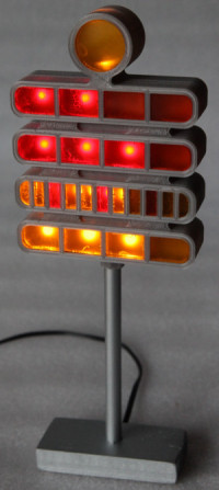
The top two rows (red) of the Berlin-Uhr are the hours, the bottom two (yellow-orange) the minutes. The seconds display flashes with a rhythm of 0.5 Hz, i.e. it is off for one second and on for one second. The top row of hours and minutes is multiplied by a factor of 5 for each field. The bottom row with a factor of 1. In the 5 minutes, every third light is red to make it easier to see quarter hours.
The clock on the pic shows 1:38 p.m. (read from above):
The clock was developed by Dieter Binninger. In addition to the technical description, his patents showss a draft for the later Berlin clock and other futuristic designs, such as the one shown.
So it's time to build such a watch yourself.
In the age of microcontrollers, the technology is of course not really a challenge. But I find that boring. You have the code together in half an hour and then of course there is also a wish list containing DCF77 , RTC , alarm clock and other stuff, simply because it would work and because otherwise the project would be a bit boring and stupid. Incidentally, the table models had a 4-bit microcontroller and offered an alarm function.
I like to indulge in (electrotechnical) nostalgia and want to build a clock made entirely from logic gates consists. In Elektor 5/1980 there was a similar circuit at the time that uses an NE555 timer as a timer and is therefore likely to be relatively imprecise, since the time base consisting of the resistor and capacitor is temperature-dependent.
After the simulation with Proteus and the drafting of a circuit diagram, I had a circuit board manufactured. The LEDs should be as bright as possible and SMD so that they are on the soldering side, while the TTL components etc. should be placed on the component side. In this way, the circuit board can later be placed in a 3D-printed housing. Contrary to the original, not two lamps / LEDs are used for you large light fields, but only one everywhere. The LEDs OF-SMD2012Y (yellow) and OF-SMD2012R (red) are quite bright with 210-270 mcd and 90-120 mcd at approx. 1.9 V and 20 mA. A wired L-7113SYCK is used for the seconds display . The circuit board is limited to the minute and hour ranges, as it is significantly cheaper than if the seconds LED is also taken into account.
In the first draft, the 24 o'clock reset was logically incorrectly linked, so that a reset did not take place until 25 o'clock. The new logic was tested on a breadboard and the errors in the circuit diagram above and the circuit board files were corrected. The board is available for download as an Eagle file in BRD format
Without a stylish exterior, the watch is only half as beautiful. I designed a 3D model and printed it with a 3D printer. The colored inlays have been cut with a laser cutter. A brass tube serves as a stand and a piece of wood forms the base. The realization is not yet completely optimal. Housing and circuit board are not exact enough, so that there is a slight offset between the LEDs and the segments, which is not really serious. It would also be better to print the case from black PLA at 100% density and then paint it to get it lightproof. The colored inlays are also not a perfect fit. Superglue ran on the edge of the surfaces and I also glued two layers on top of each other, just like placing a handkerchief as a diffuser in front of the LEDs. Still, the replica looks good and most importantly, it is really accurate.
More information with a detailed description of the logical gates on blafusel.de in German
The clock on the pic shows 1:38 p.m. (read from above):
  2 x 5 hours = 10
+ 3 x 1 hour  = 3
              = 13 (1 p.m.)

  7 x 5 minutes = 35
+ 3 x 1 minute  = 3
                = 38 minutes
The clock was developed by Dieter Binninger. In addition to the technical description, his patents showss a draft for the later Berlin clock and other futuristic designs, such as the one shown.
So it's time to build such a watch yourself.
In the age of microcontrollers, the technology is of course not really a challenge. But I find that boring. You have the code together in half an hour and then of course there is also a wish list containing DCF77 , RTC , alarm clock and other stuff, simply because it would work and because otherwise the project would be a bit boring and stupid. Incidentally, the table models had a 4-bit microcontroller and offered an alarm function.
I like to indulge in (electrotechnical) nostalgia and want to build a clock made entirely from logic gates consists. In Elektor 5/1980 there was a similar circuit at the time that uses an NE555 timer as a timer and is therefore likely to be relatively imprecise, since the time base consisting of the resistor and capacitor is temperature-dependent.
After the simulation with Proteus and the drafting of a circuit diagram, I had a circuit board manufactured. The LEDs should be as bright as possible and SMD so that they are on the soldering side, while the TTL components etc. should be placed on the component side. In this way, the circuit board can later be placed in a 3D-printed housing. Contrary to the original, not two lamps / LEDs are used for you large light fields, but only one everywhere. The LEDs OF-SMD2012Y (yellow) and OF-SMD2012R (red) are quite bright with 210-270 mcd and 90-120 mcd at approx. 1.9 V and 20 mA. A wired L-7113SYCK is used for the seconds display . The circuit board is limited to the minute and hour ranges, as it is significantly cheaper than if the seconds LED is also taken into account.
In the first draft, the 24 o'clock reset was logically incorrectly linked, so that a reset did not take place until 25 o'clock. The new logic was tested on a breadboard and the errors in the circuit diagram above and the circuit board files were corrected. The board is available for download as an Eagle file in BRD format
Without a stylish exterior, the watch is only half as beautiful. I designed a 3D model and printed it with a 3D printer. The colored inlays have been cut with a laser cutter. A brass tube serves as a stand and a piece of wood forms the base. The realization is not yet completely optimal. Housing and circuit board are not exact enough, so that there is a slight offset between the LEDs and the segments, which is not really serious. It would also be better to print the case from black PLA at 100% density and then paint it to get it lightproof. The colored inlays are also not a perfect fit. Superglue ran on the edge of the surfaces and I also glued two layers on top of each other, just like placing a handkerchief as a diffuser in front of the LEDs. Still, the replica looks good and most importantly, it is really accurate.
More information with a detailed description of the logical gates on blafusel.de in German
Discussie (3 opmerking(en))