
ESP32 Serial Terminal
Many times like a multimeter, I expected to have a handy serial terminal nearby such that I will connect those two wires [Tx, Rx] of the probe and will be able to see whether the sensor is really sending any output or not. The sensor may communicate on 9600 bps or 4800 bps or even 2400 bps which I may not know. I will just flip a switch to those marks and I will come to know on which speed it communicates. The output displays on a small TFT screen.
ESP32 Serial Terminal Monitor
Prelude: Many times like a multimeter, I expected to have a handy serial terminal nearby such that I will connect those two wires [Tx, Rx] of the probe and will be able to see whether the sensor is really sending any output or not. The sensor may communicate on 9600 bps or 4800 bps or even 2400 bps which I may not know. I will just flip a switch to those marks and I will come to know on which speed it communicates. The device will have a small TFT screen on which the communications will be appearing. Such type of sensors are - GPS sensors, Bluetooth modules [HC-05, HC-06], RFID readers, Inertia Measuring Units - accelerator MPU6050, Barometric pressure sensors - BMP180, BMP280, IR Receivers such as TSOP4838, RFID readers like MFRC522, Cellular modules like SIM800L or SIM900, RF Transceivers like LoRa transceivers, nRF24L01 etc. For all these sensors, besides power supply it will have a distinct Tx & Rx line to transfer data.
Project idea: Well on an Arduino UNO if the sensor is connected to the Tx, Rx pin and it’s supply line with Uno’s 5V / 3.3V & ground pin and the sketch is made such a way that if something is read on Serial terminal, it must reproduce on the serial terminal…
if (Serial.available() > 0) {String rs = Serial.readStringUntil('\n'); // Read the string until newline characterSerial.println(rs);char cs = Serial.read(); // read anything that arrives Serial.println(cs);}
That’s it. However, the only problem is that we need to have a computer connected to the Uno with the Arduino IDE installed. Just to get rid of this cumbursome setup this handy Serial monitor will work!
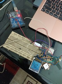
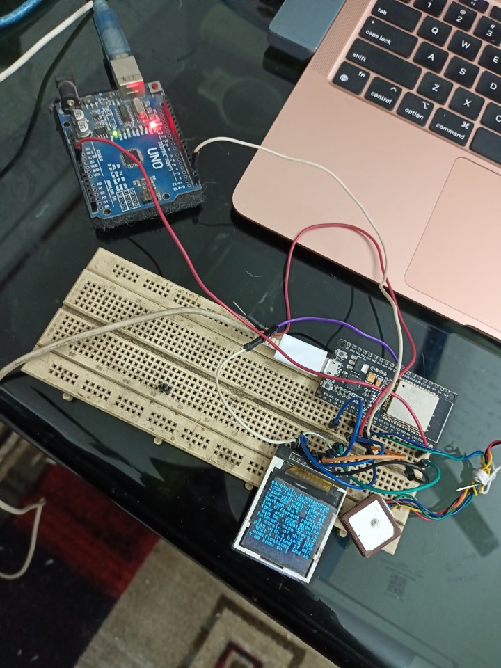
Our Device: Exactly does this whole thing minus the computer & allied wires. See it here.
Pic:
Schematic:
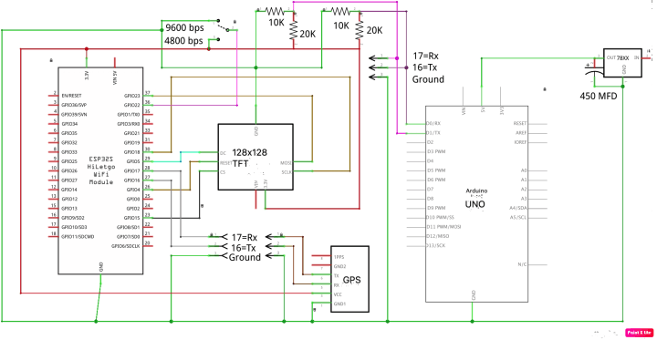
Project: A small 128x128 TFT is connected to the ESP32 on SPI. GPIO pin 16, 17 is designated as Serial terminal at variable BPS [Bits per second]. GPIO pin 22 is selected as input pin for variable BPS setup. When Pin-22 is connected to ground, the BPS is set to 9600 bps. If it is connected to +ve, the BPS is set up to 4800. However, after flipping the switch, we have to restart the device to take the BPS into effect as the BPS setup is actuated in the setup loop. To set up more variable speeds [BPS] we may deploy more GPIO pins in similar way. However, most of the modern sensors works in either of these two speeds [4800 or 9600].
The Tx, Rx and Ground pins are to be connected with the Rx, Tx & Ground pins of the UART sensors. This is shown in the schematic. The ESP32 is a 3.3 volt device. Therefore, the 5Volt signals of Arduino or other 5 volt sensors to be voltage divided to 3.3 volt level using 10K & 20K resistors pairs.
Programming: Here lies the actual power of this device. We have cleverly asked the ESP32 to check it’s internal serial terminal and spew out whatever arrives there!
if (Serial2.available()) { char ca = Serial2.read(); Serial.print(ca); display.print(ca); if(display.getCursorY() >= height ) { display.clearScreen();display.setCursor(0,0); } }While doing so it continuously checks the the cursor_Y position and the moment it touches the entire width, it clears the screen and rolls back to the 0,0 position and continues the cycle.
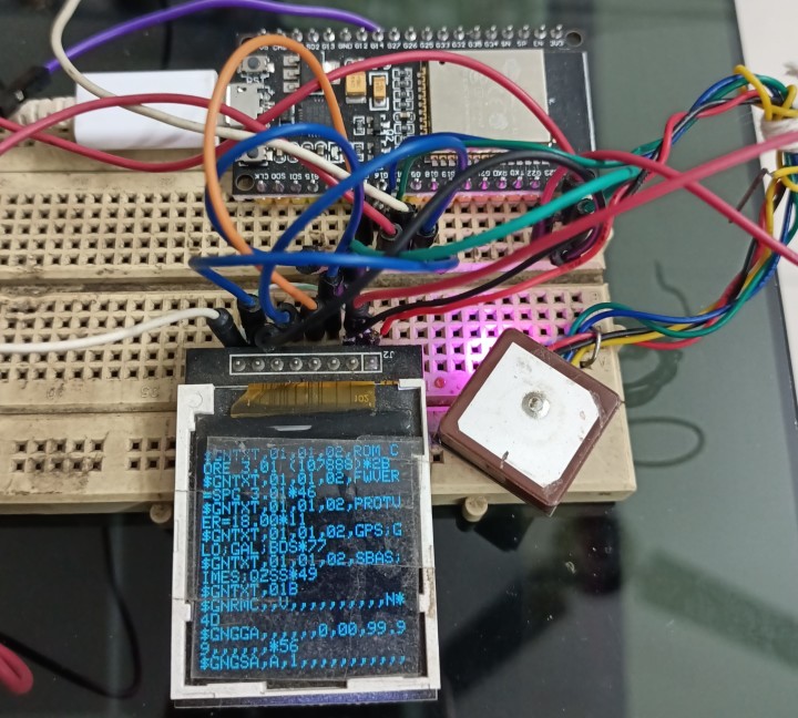
Testing: Testing of the circuit is fairly easy. Just connect any UART sensor to the TX, Rx, Gnd terminal of ESP32. Set the BPS to 9600 or 4800 [I hope majority of the sensors will cover in this range, if not another 1200 / 2400 may be added later by the reader, as some LoRa sensors works longer distance on 2400 or even 1200 BPS] and check the TFT of data arrival! In the laboratory testing we used a GPS sensor and an Arduino UNO device. Both successfully sends data flawlessly. The small Arduino UNO terminal sender program is made to transfer Serial terminal data to the ESP32 Serial terminal only. This sketch is also attached herewith for ready references.
Attachment: Arduino sketch for ESP32 Serial terminal, Arduino USO sender terminal sketch, Arduino Libraries.
Kolkata
Somnath Bera
Prelude: Many times like a multimeter, I expected to have a handy serial terminal nearby such that I will connect those two wires [Tx, Rx] of the probe and will be able to see whether the sensor is really sending any output or not. The sensor may communicate on 9600 bps or 4800 bps or even 2400 bps which I may not know. I will just flip a switch to those marks and I will come to know on which speed it communicates. The device will have a small TFT screen on which the communications will be appearing. Such type of sensors are - GPS sensors, Bluetooth modules [HC-05, HC-06], RFID readers, Inertia Measuring Units - accelerator MPU6050, Barometric pressure sensors - BMP180, BMP280, IR Receivers such as TSOP4838, RFID readers like MFRC522, Cellular modules like SIM800L or SIM900, RF Transceivers like LoRa transceivers, nRF24L01 etc. For all these sensors, besides power supply it will have a distinct Tx & Rx line to transfer data.
Project idea: Well on an Arduino UNO if the sensor is connected to the Tx, Rx pin and it’s supply line with Uno’s 5V / 3.3V & ground pin and the sketch is made such a way that if something is read on Serial terminal, it must reproduce on the serial terminal…
if (Serial.available() > 0) {String rs = Serial.readStringUntil('\n'); // Read the string until newline characterSerial.println(rs);char cs = Serial.read(); // read anything that arrives Serial.println(cs);}
That’s it. However, the only problem is that we need to have a computer connected to the Uno with the Arduino IDE installed. Just to get rid of this cumbursome setup this handy Serial monitor will work!
Our Device: Exactly does this whole thing minus the computer & allied wires. See it here.
Pic:
Schematic:
Project: A small 128x128 TFT is connected to the ESP32 on SPI. GPIO pin 16, 17 is designated as Serial terminal at variable BPS [Bits per second]. GPIO pin 22 is selected as input pin for variable BPS setup. When Pin-22 is connected to ground, the BPS is set to 9600 bps. If it is connected to +ve, the BPS is set up to 4800. However, after flipping the switch, we have to restart the device to take the BPS into effect as the BPS setup is actuated in the setup loop. To set up more variable speeds [BPS] we may deploy more GPIO pins in similar way. However, most of the modern sensors works in either of these two speeds [4800 or 9600].
The Tx, Rx and Ground pins are to be connected with the Rx, Tx & Ground pins of the UART sensors. This is shown in the schematic. The ESP32 is a 3.3 volt device. Therefore, the 5Volt signals of Arduino or other 5 volt sensors to be voltage divided to 3.3 volt level using 10K & 20K resistors pairs.
Programming: Here lies the actual power of this device. We have cleverly asked the ESP32 to check it’s internal serial terminal and spew out whatever arrives there!
if (Serial2.available()) { char ca = Serial2.read(); Serial.print(ca); display.print(ca); if(display.getCursorY() >= height ) { display.clearScreen();display.setCursor(0,0); } }While doing so it continuously checks the the cursor_Y position and the moment it touches the entire width, it clears the screen and rolls back to the 0,0 position and continues the cycle.
Testing: Testing of the circuit is fairly easy. Just connect any UART sensor to the TX, Rx, Gnd terminal of ESP32. Set the BPS to 9600 or 4800 [I hope majority of the sensors will cover in this range, if not another 1200 / 2400 may be added later by the reader, as some LoRa sensors works longer distance on 2400 or even 1200 BPS] and check the TFT of data arrival! In the laboratory testing we used a GPS sensor and an Arduino UNO device. Both successfully sends data flawlessly. The small Arduino UNO terminal sender program is made to transfer Serial terminal data to the ESP32 Serial terminal only. This sketch is also attached herewith for ready references.
Attachment: Arduino sketch for ESP32 Serial terminal, Arduino USO sender terminal sketch, Arduino Libraries.
Kolkata
Somnath Bera
Discussie (1 opmerking(en))